
Water-gas co-containment cabin electric energy storage system with constant pressure of high-pressure gas storage tank

A technology of electric energy storage system and high-pressure gas storage tank, which is applied in the fields of hydroelectric power generation, liquid variable capacity machinery, pump control, etc. It can solve the problems of co-capacity and other problems, so as to solve the problem of water pressure stability and improve the density of energy storage.

Active Publication Date: 2016-08-24
XI AN JIAOTONG UNIV
View PDF6 Cites 4 Cited by
  • Summary
  • Abstract
  • Description
  • Claims
  • Application Information

AI Technical Summary

Problems solved by technology

[0007] However, in the process of the steam boiler replenishing water vapor into the water-gas compatible cabin, since the high-temperature steam enters the water-gas compatible cabin, the water temperature, gas temperature and environment in the water-gas compatible cabin The temperature is similar, and the high-temperature water vapor will inevitably exchange heat with the medium in the water-gas coexistence chamber. The increase of the gas temperature will reduce the safety of the water-gas coexistence chamber, accelerate the corrosion of the water-gas coexistence chamber, and greatly reduce its The working life and the overall thermal cycle are complicated. In addition, the use of steam boilers also makes the system structure more complicated, and the economy and environmental protection become worse.

Method used


Image

  • Water-gas co-containment cabin electric energy storage system with constant pressure of high-pressure gas storage tank
  • Water-gas co-containment cabin electric energy storage system with constant pressure of high-pressure gas storage tank

Examples


Embodiment Construction

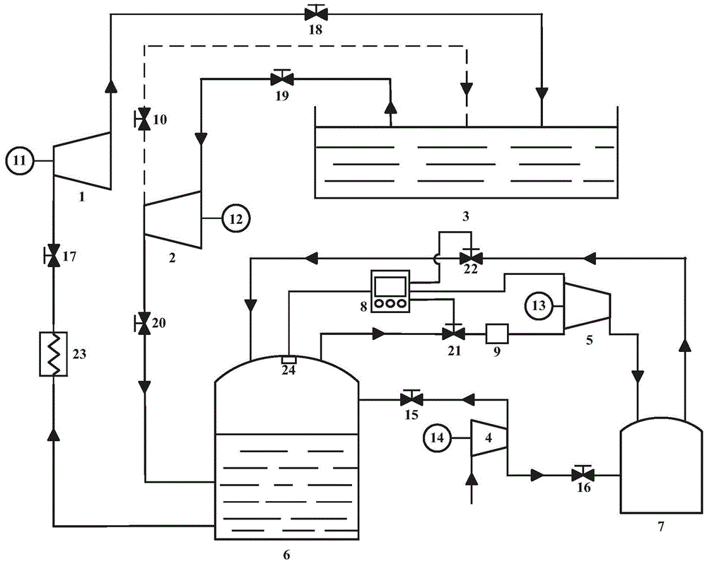
[0019] like figure 1 As shown, the constant pressure water-gas co-containment cabin power energy storage system of the present invention includes a compressor unit 4 driven by a compression motor 14, a water pump unit 2 driven by a water pump motor 12, a water storage tank 3 connected to the atmosphere above and a driveable The water turbine 1 used by the generator 11 generates electricity, and the outlet of the water turbine 1 provides water for the storage tank through the pipeline and the valve 18, and the water pump unit 2 pumps water from the water storage tank through the pipeline and the valve 19.

[0020] An outlet of the compressor unit 4 communicates with the upper part of the water-air compatible cabin 6 through a pipeline and a valve 15, and the outlet of the water pump unit 2 communicates with the middle part of the water-gas compatible cabin through a pipeline and a valve 20. The outlet of the lower part of the water-gas co-containment cabin 6 is connected to the...


PUM


Abstract

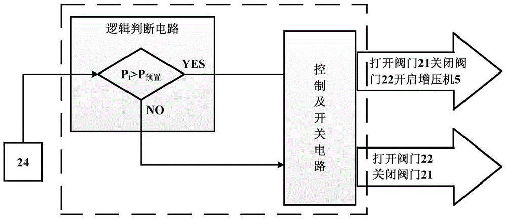
The invention discloses a water-gas common-cabin electric power energy storage system utilizing a high pressure gasholder to maintain constant pressure. The water-gas common-cabin electric power energy storage system comprises a water-gas common-cabin, a compressor unit, a water pump unit, a water storage pool and a water turbine, wherein a water exhaust port of the water turbine supplies inlet water to the water storage pool through a pipeline, the water pump unit pumps water from the water storage pool through a pipeline, a gas exhaust port of the gas compressor unit is communicated with the water-gas common-cabin, a water outlet of the water-gas common-cabin is communicated with the water turbine, and a generator is driven by the water turbine to generate electricity for outputting electric energy. The water-gas common-cabin electric power energy storage system is characterized by also comprising a supercharger and the high pressure gasholder, wherein the high pressure gasholder is connected with two pipelines, one pipeline is communicated with an outlet at the upper part of the water-gas common-cabin through the supercharger, a water and gas separator and a first electric control valve, and the other pipeline is communicated with an inlet at the upper part of the water-gas common-cabin through a second electric control valve.

Description

technical field [0001] The invention relates to a system for physical energy storage of electric energy, in particular to a system for realizing electric energy storage by utilizing a water-air coexistence chamber. Background technique [0002] With the depletion of traditional fossil energy, the utilization of renewable energy has been paid more and more attention. The development of renewable energy has become a top priority in many countries. However, the inherent randomness and volatility of renewable energy such as wind energy, solar energy, and biomass have brought great challenges to the development of new energy sources around the world. How to solve the volatility of renewable energy is the key to the development and utilization of renewable energy. In recent years, China's wind power and solar power have developed rapidly. Since 2010, China's wind power installed capacity has leapt to the first place in the world. By the end of 2013, China's cumulative installed ...

Claims


Application Information

Patent Timeline
Patent Type & Authority Patents(China)
IPC IPC(8): F03B13/06F04B41/02F04B49/06F04B49/22
CPCY02E10/20Y02E60/16
Inventor 王焕然姚尔人柳龙席光
Owner XI AN JIAOTONG UNIV
Learn More