
Quiescent current control device

A quiescent current and control device technology, applied in control/regulation systems, output power conversion devices, electrical components, etc. Small impact, the effect of increasing bandwidth

Inactive Publication Date: 2014-10-15
UNIV OF ELECTRONICS SCI & TECH OF CHINA
View PDF7 Cites 3 Cited by
  • Summary
  • Abstract
  • Description
  • Claims
  • Application Information

AI Technical Summary

Problems solved by technology

The disadvantage of this control method is the low gain, so in order to ensure the stability of the loop, it is not conducive to bandwidth expansion, so there will be crossover distortion at high frequency input

Method used


Image

  • Quiescent current control device
  • Quiescent current control device
  • Quiescent current control device

Examples


Embodiment

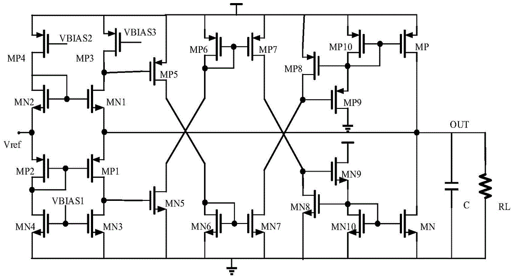
[0017] Such as image 3 As shown, the push-pull output stage circuit consists of PMOS tubes MP, MP1, MP2, MP3, MP4, MP5, MP6, MP7, MP8, MP9, MP10, NMOS tubes MN, MN1, MN2, MN3, MN4, MN5, MN6, MN7 . The drain is connected to the source of MP9 and the gate of MP8; the source of MP8 is connected to the power supply, and its drain is connected to the gate of MP9 and the drain of MN7; the drain of MP9 is grounded; the drain of MP7 The source is connected to the power supply, its gate is connected to the gate of MP6, and its drain is connected to the drain of MN8 and the gate of MN9; the source of MP6 is connected to the power supply, its gate and drain are interconnected, and its drain is connected to the MN5 Drain; the source of MP5 is connected to the power supply, its gate is connected to the drain of MP3, and its drain is connected to the drain of MN6; the source of MP3 is connected to the power supply, its gate is connected to the third bias voltage, and its drain is connecte...


PUM


Abstract

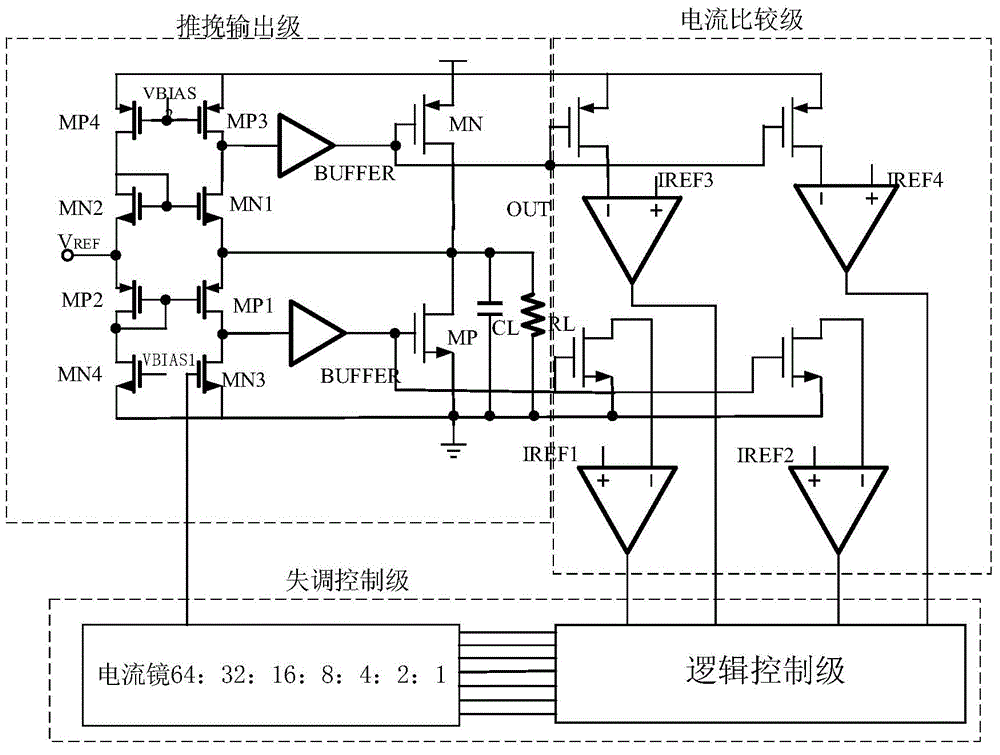
The invention relates to the technical field of analog integrated circuits, in particular to a quiescent current control device. The quiescent current control device comprises a push-pull output stage circuit, a current comparator and an offset controller; the offset controller is respectively connected with the push-pull output stage circuit and the current comparator; the push-pull output stage circuit is used for determining the output voltage and simultaneously amplifying the error of an output point with an input voltage for further providing current for the load or for further drawing off current from the load; the current comparator adjusts the offset voltage to control the quiescent current by sampling the current of an upper and a lower common source electrode transistors, comparing the current of the upper and the lower common source electrode transistors with the reference current, and sending comparison results to the offset controller which controls the current mirror ratio through a digital control module. The quiescent current control device has the advantages of being simple in circuit structure, omitting a complex feedback control circuit, being capable of effectively improving the bandwidth, and reducing the impact of process and temperature deviation. The quiescent current control device is applicable.

Description

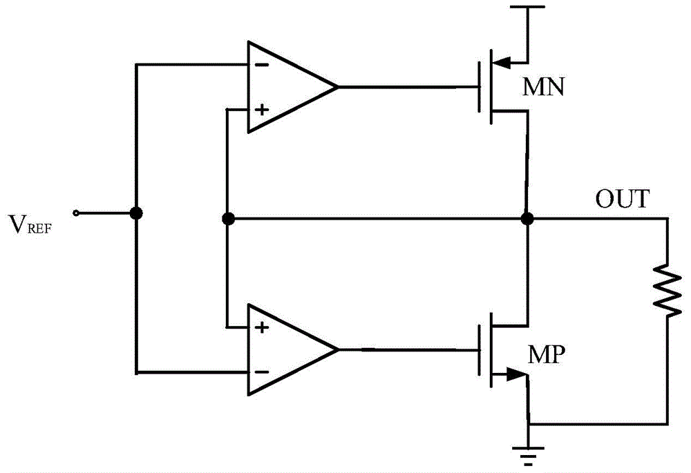
technical field [0001] The invention belongs to the technical field of analog integrated circuits, and in particular relates to a static current control device. Background technique [0002] Complementary Class A and B output stage circuits for common-source output devices, see figure 1 As shown, due to its large output swing, low output impedance and the advantages of providing current to the load and drawing current from the load, it is widely used. But a non-zero bias voltage in the error amplifier changes the quiescent current in the output transistor. Although further increasing the quiescent current can reduce the crossover distortion, it will increase the loss of power consumption and reduce the output voltage swing. Therefore, at zero load, effective control of quiescent current becomes a critical issue. [0003] At present, there are mainly two methods for controlling the quiescent current. One works by sampling the output current and feeding it back. By introd...

Claims


Application Information

Patent Timeline
IPC IPC(8): H02M3/157
Inventor 甄少伟王磊杨云许志斌罗萍贺雅娟张波
Owner UNIV OF ELECTRONICS SCI & TECH OF CHINA
Learn More