Thermal protection element and manufacturing method thereof

A thermoelectric protection and heating element technology, applied in electrical components, thermal switch parts, circuits, etc., can solve the problems of inaccurate welding positioning, low production yield, increased three-dimensional space occupation, etc., and achieve low manufacturing costs and production. High yield and space saving effect

Active Publication Date: 2016-04-27
上海神沃电子有限公司
View PDF4 Cites 0 Cited by
  • Summary
  • Abstract
  • Description
  • Claims
  • Application Information

AI Technical Summary

Problems solved by technology

This type of product has the following disadvantages: 1. The structure is complex, the assembly precision is high, and the production yield is low. Due to the existence of pins, the overall processing must have a special pin installation and assembly process, and the process requires high-precision positioning. Increased cost and limited production efficiency; 2. Non-surface mount design leads to a large area occupied by integrated circuits, which is not conducive to the installation of large-scale integrated circuits. The electronic industry is becoming increasingly integrated, and the lead-out pins of electronic components increase the overall The invalid area of ​​the component occupies the space of the integrated circuit. Even if the projection on the two-dimensional plane is reduced to the minimum through the bending design, on the other hand it increases the occupancy of the three-dimensional space, so the pin-type design has obvious defects; 3. Non-surface mount design results in inefficient soldering process and inaccurate soldering positioning
The modern electronics industry widely uses reflow soldering to improve production efficiency and reduce defective rate. Leaded components are mostly suitable for spot welding, which has poor adaptability to surface mount technology and is prone to displacement.
[0003] The circuit breakers with thermal protection functions currently used in the market all have the above-mentioned shortcomings, such as bimetallic thermal protectors, PTC thermal protectors, Breaker thermal protectors, electronic circuit thermal protectors, etc., among which Breaker thermal protectors Combining the common advantages of bimetallic sheet and PTC, it also preliminarily realizes the miniaturization design, but its lead electrode design has a large projected area and complex structure, which limits its production efficiency and application range
[0004] The Chinese Invention Patent Application Specification with the application number 201110457077.8 discloses a self-holding overcurrent protection device, which is a typical dual-pin thermoelectric protection element. Volume, but the structure is complicated, it must be installed precisely, the projected area is large, and it is not suitable for mass production and surface mount technology

Method used


Image

  • Thermal protection element and manufacturing method thereof
  • Thermal protection element and manufacturing method thereof
  • Thermal protection element and manufacturing method thereof

Examples


Embodiment Construction

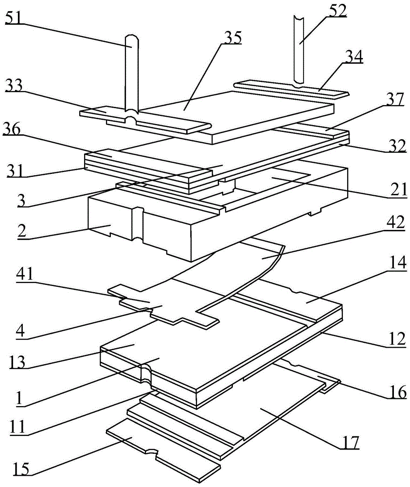
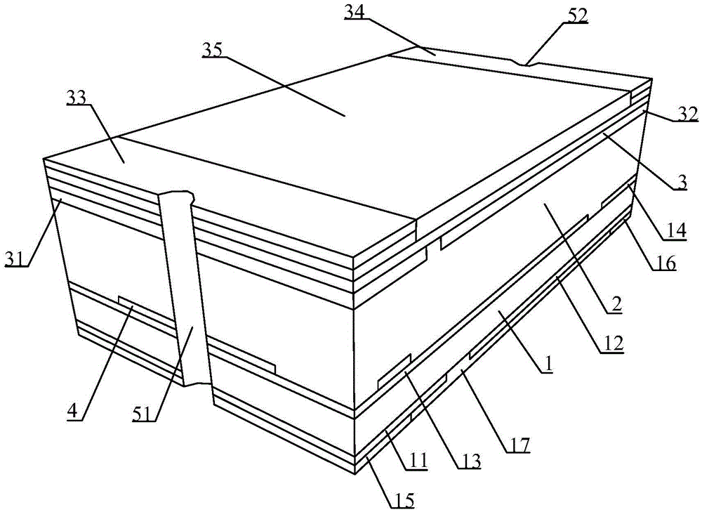
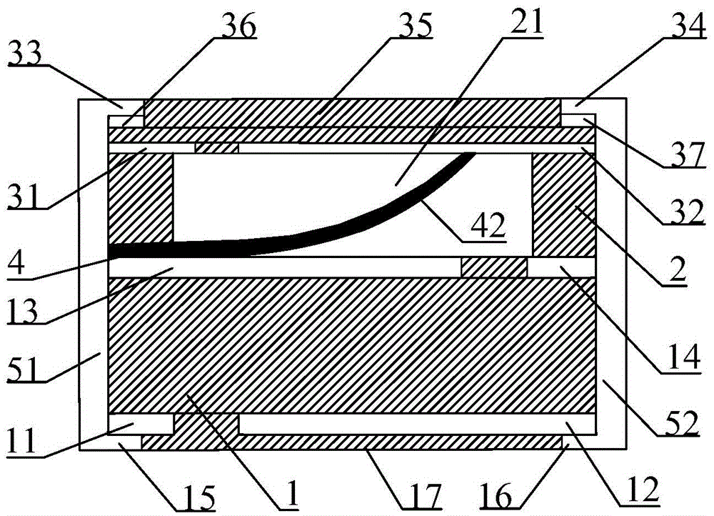
[0049] The specific implementation manners of the present invention will be described in further detail below in conjunction with the accompanying drawings. These embodiments are only used to help the understanding of the present invention, but not to limit the present invention.

[0050] In the description of the present invention, it should be noted that the orientations or positional relationships indicated by the terms "upper", "lower", "top", "bottom", "left", "right" etc. are based on the orientations shown in the drawings Or positional relationship is only for the convenience of describing the present invention and simplifying the description, but does not indicate or imply that the device or element referred to must have a specific orientation, be constructed and operated in a specific orientation, and therefore should not be construed as limiting the present invention. In addition, the terms "first", "second", etc. are only used to distinguish different technical feat...


PUM


Abstract

The invention discloses a thermoelectric protection element and a manufacturing method thereof. The thermoelectric protection element comprises a heating element, an insulated shell and an upper cover plate sequentially stacked from the bottom top, wherein the bottom surface of the heating element is provided with a first left electrode and a first right electrode; the top surface of the heating element is provided with a second left electrode and a second right electrode; the bottom surface of the upper cover plate is provided with a third left electrode and a third right electrode; the insulated shell is internally provided with a first cavity; the fixed end of a thermal drive switch is clamped between the bottom surface of the insulated shell and the second left electrode; and the moving end of the thermal drive switch is located inside the cavity of the insulated shell and is electrically contacted with the third right electrode in a normal state. The thermoelectric protection element also comprises a first left pad, a first right pad, a second left pad, a second right pad, a left-end electrode and a right-end electrode. According to the thermoelectric protection element, the structure is simple, large-scale automatic production is facilitated, the manufacturing cost is low, the element area is small, space is saved, and the thermoelectric protection element can be applied to the integrated circuit surface-mount technology.

Description

technical field [0001] The invention relates to a thermoelectric protection element and a manufacturing method thereof, in particular to a surface mount type thermoelectric protection element and a manufacturing method thereof. Background technique [0002] Thermal protection components are widely used in various electronic and electrical equipment in industry and household. There are many kinds of circuit breakers with thermal protection function in the market, but all of them are lead-type electrode products. This type of product has the following disadvantages: 1. The structure is complex, the assembly precision is high, and the production yield is low. Due to the existence of pins, the overall processing must have a special pin installation and assembly process, and the process requires high-precision positioning. Increased cost and limited production efficiency; 2. Non-surface mount design leads to a large area occupied by integrated circuits, which is not conducive to ...

Claims


Application Information

Patent Timeline
Patent Type & Authority Patents(China)
IPC IPC(8): H01H37/02H01H37/52H01H11/00
Inventor 赵亮侯李明任井柱符林祥臧育锋
Owner 上海神沃电子有限公司
Why Eureka
Try Eureka