Waiting time relaxation based conflict resolution method and optimization scheduling method

A waiting time and conflict resolution technology, applied in the direction of comprehensive factory control, comprehensive factory control, electrical program control, etc., can solve problems such as increasing the computational workload, affecting the production efficiency of the converter, and the success rate of resolving equipment conflicts cannot be guaranteed.

Active Publication Date: 2014-10-29
WISDRI ENG & RES INC LTD
View PDF6 Cites 6 Cited by
  • Summary
  • Abstract
  • Description
  • Claims
  • Application Information

AI Technical Summary

Problems solved by technology

This method takes advantage of the statistical characteristics of operating time distribution. Although it is theoretically feasible, it has the following disadvantages in practical application: First, for a mature converter steelmaking plant, taking the converter smelting process as an example, the The blowing time is generally strictly controlled within 28 minutes (about 10 minutes not including the auxiliary time). If the above rule-based conflict resolution method is used to resolve equipment conflicts and artificially shorten or prolong the processing time of the converter smelting process, it will It is not feasible, because shortening the processing time will cause the molten stee

Method used


Image

  • Waiting time relaxation based conflict resolution method and optimization scheduling method
  • Waiting time relaxation based conflict resolution method and optimization scheduling method
  • Waiting time relaxation based conflict resolution method and optimization scheduling method

Examples


Embodiment Construction

[0075] The present invention will be further described below in conjunction with specific examples and accompanying drawings.

[0076] The conventional converter steelmaking process includes: desulfurization (KR), converter smelting (LD), argon blowing (Ar), ladle furnace (LF), vacuum refining (RH) and continuous casting (CC). The following process prerequisites are met:

[0077] 1) Different steel types correspond to different processing paths, and will go through all or part of the above-mentioned process links in sequence, such as KR→LD→Ar→CC, KR→LD→LF→RH→CC, etc., but there is no loopback on the process path , that is, it will not go through the same process twice, and the situation of returning to furnace and changing steel is not considered here.

[0078] 2) The time of molten steel in the converter steelmaking plant is divided into the following categories: the processing time of the process (including auxiliary time), the transportation time between adjacent processes...


PUM


Abstract

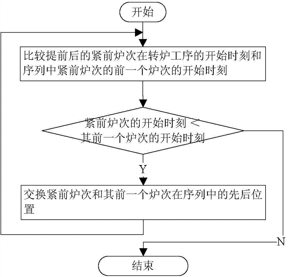
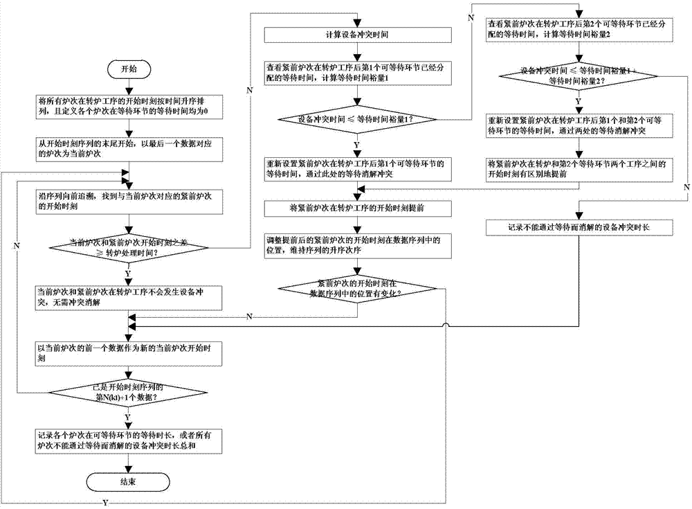
The invention provides a waiting time relaxation based conflict resolution method. The waiting time relaxation based conflict resolution method comprises adjusting the waiting time length of the furnace number before the process which can be waited for through iterative relaxation to completely resolve the equipment conflict; ranking the beginning time of the furnace numbers in the converter process according to the time ascending order to obtain a beginning time sequence, setting an initial value of the waiting time of the furnace numbers in the buffering process to be zero and serving the furnace number which is corresponding to the last datum as the current furnace number; judging whether the equipment conflict occurs between the current furnace number and the closely previous furnace number in the converter process or not, serving the corresponding furnace number of the previous datum of the beginning time of the current furnace number as the new current furnace number and continuing if not and computing the equipment conflict time, checking the assigned waiting time of the closely previous furnace number in the buffering process after the converter process, computing the waiting time margin and adjusting the waiting time through the iterative relaxation to resolve the equipment conflict if yes. According to the waiting time relaxation based conflict resolution method and optimization scheduling method, the requirements of the optimization scheduling scheme under the busy and complex work conditions can be well met and the production efficiency of a converter steel mill is improved.

Description

technical field [0001] The invention is applied to the steelmaking-continuous casting production process, and is specifically a conflict resolution method and an optimal scheduling method based on waiting time relaxation. Background technique [0002] The steelmaking-continuous casting production process is the core link in the production process of modern iron and steel complexes. In this production process, the molten iron from the blast furnace is first smelted into high-temperature molten steel by converter or electric furnace, and then refined by a refining furnace to meet the requirements of molten steel. The chemical composition and temperature requirements are finally sent to the continuous casting machine to be cast into slabs or billets of different specifications. The improvement of production efficiency in the steelmaking-continuous casting production process has an important impact on the entire iron and steel enterprise, and making a reasonable production sched...

Claims


Application Information

Patent Timeline
IPC IPC(8): G05B19/418
CPCY02P90/02
Inventor 曾亮
Owner WISDRI ENG & RES INC LTD
Why Eureka
Try Eureka