Labyrinth type oil-gas separation chamber with additionally mounted turbine

A technology of oil and gas separation chamber and oil and gas separator, which is applied in the direction of engine components, machines/engines, mechanical equipment, etc., which can solve the problems of reducing the lubricating effect of engine oil in the crankcase, increasing the PM emission of the engine, and damaging the air filter element and other problems, to achieve the effect of increasing flow rate, increasing pressure and improving efficiency

Active Publication Date: 2014-11-05
HANGZHOU DIANZI UNIV
View PDF4 Cites 4 Cited by
  • Summary
  • Abstract
  • Description
  • Claims
  • Application Information

AI Technical Summary

Problems solved by technology

In the crankcase forced ventilation system, the blow-by gas of the engine piston must be recovered into the intake pipe, which requires that there be no oil droplets in the recovered gas as much as possible. If the oil in the "bypass mixture" cannot be cleaned, it will affect the The combustion of the engine will damage the filter element of the air filter, which will lead to the increase of the PM emission of the engine and the clogging of the air filter.

Method used


Image

  • Labyrinth type oil-gas separation chamber with additionally mounted turbine
  • Labyrinth type oil-gas separation chamber with additionally mounted turbine

Examples


Embodiment Construction

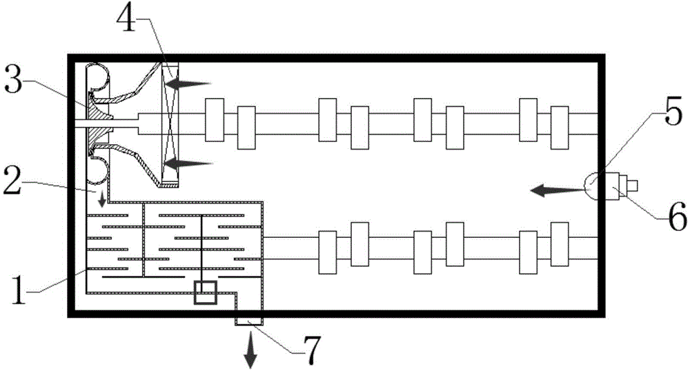
[0017] The invention relates to the oil-gas separation structure design of a cam chamber in the engine crankcase ventilation, and aims to provide a simple and effective oil-gas separation chamber structure.

[0018] Such as figure 1 As shown, the structure mainly includes a labyrinth oil-gas separator 1, a pressure regulating valve 6, a non-woven filter element 4 and a turbine 3:

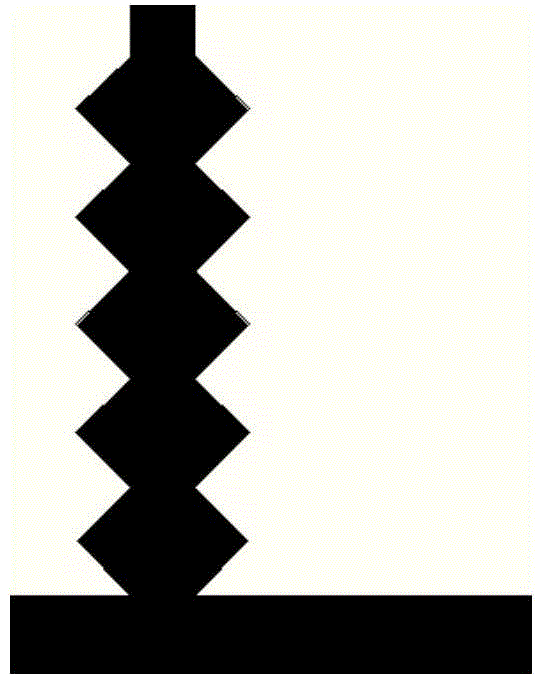
[0019] The labyrinth oil-gas separator has a toothed baffle made of engineering plastics, which is assembled inside the cylinder head in a certain structural design and connected to the turbine outlet to increase the impact of the oil particles in the mixed oil mist on the wall. Probability, can make the oil particles condense, adhere and merge, and return the oil through the oil return tank, and the outlet of the oil-gas separator can also be connected to other oil-gas separation devices outside the machine to further improve the oil-gas separation efficiency.

[0020] The pressure regulating valv...


PUM


Abstract

The invention relates to a labyrinth type oil-gas separation chamber with an additionally mounted turbine. The labyrinth type oil-gas separation chamber comprises a labyrinth oil-gas separator, a pressure adjusting valve, a non-woven filter element and the turbine. The pressure adjusting valve is arranged on the wall of the labyrinth type oil-gas separation chamber, and mixed oil mist from a crankcase enters the labyrinth type oil-gas separation chamber through the pressure adjusting valve and a mixed oil mist inlet. The turbine is assembled at a free end of a camshaft, the nonwoven filter element capable of filtering oil and water in mixed gas is arranged in an inlet of the turbine, and an outlet of the turbine is connected with the labyrinth type oil-gas separation chamber through a connector. An indented baffle made of engineering plastics is arranged in the labyrinth type oil-gas separator. The temperature of flowing oil mist in a labyrinth is effectively decreased by rotation of the turbine, flow rate of the oil mist is increased, condensation speed of elaioplast is increased, and pressure at a gas outlet is increased.

Description

technical field [0001] The invention relates to a labyrinth type oil-gas separation chamber, in particular to a labyrinth type oil-gas separation chamber equipped with a turbine. Background technique [0002] With the increasing demand for energy saving and emission reduction, the emission regulations are becoming more and more stringent, and the crankcase forced ventilation system has gradually been adopted in vehicle engines. In the crankcase forced ventilation system, the blow-by gas of the engine piston must be recovered into the intake pipe, which requires that there be no oil droplets in the recovered gas as much as possible. If the oil in the "bypass mixture" cannot be cleaned, it will affect the The combustion of the engine will damage the filter element of the air filter, which will lead to the increase of the PM emission of the engine and the clogging of the air filter. This part of the residual exhaust gas must be quickly discharged from the crankcase to ensure t...

Claims


Application Information

Patent Timeline
Patent Type & Authority Applications(China)
IPC IPC(8): F01M13/04
Inventor 刘忠民王世峰
Owner HANGZHOU DIANZI UNIV
Why Eureka
Try Eureka