Method for T-shaped magnesium alloy section friction stir welding

A technology of friction stir welding and welding method, which is applied in welding equipment, non-electric welding equipment, metal processing equipment, etc., can solve the problem of low connection strength, and achieve the effects of strong thickness adaptability, high efficiency, and small heat-affected zone

Inactive Publication Date: 2014-11-12
BEIJING INSTITUTE OF TECHNOLOGYGY
View PDF3 Cites 19 Cited by
  • Summary
  • Abstract
  • Description
  • Claims
  • Application Information

AI Technical Summary

Problems solved by technology

[0004] Aiming at the problem of low connection strength of existing magnesium alloy T-shaped joints, the object of

Method used


Image

  • Method for T-shaped magnesium alloy section friction stir welding
  • Method for T-shaped magnesium alloy section friction stir welding
  • Method for T-shaped magnesium alloy section friction stir welding

Examples


Example Embodiment

[0026] Example 1

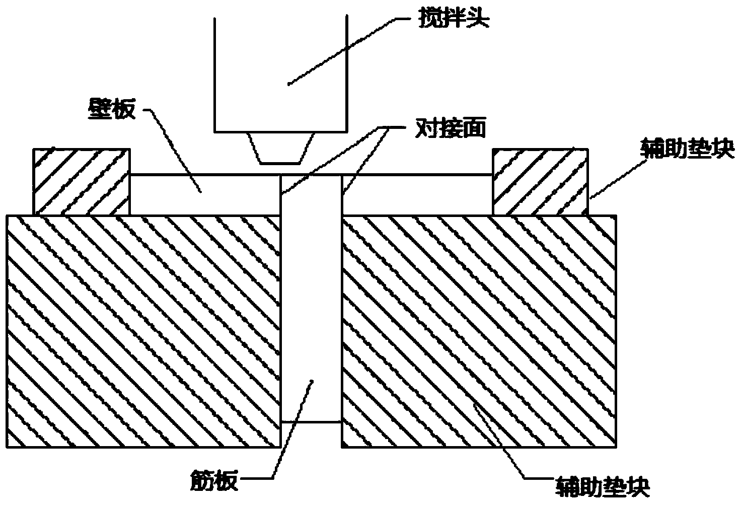
[0027] The 12mm thick AZ31 magnesium alloy is subjected to friction stir T-welding. The size of the two wall plates is 290mm×115mm×12mm, the size of the ribs is 290mm×230mm×12mm, and the tensile strength of the base material (magnesium alloy) is 268MPa. The shaft shoulder of the stirring head used is in the shape of a double-concave circular ring with a diameter of 24mm; the stirring needle is a conical right-handed thread shape with a diameter of 5-7mm and a length of 11.7mm. The three plates to be welded are butt-fixed on the backing plate with auxiliary pads, and then using tooling, the auxiliary pads of the wall plates, the three magnesium alloy profiles to be welded and the auxiliary pads of the ribs are clamped horizontally on the welding table on. At the beginning of welding, the stirring head is inserted into the butt surface of the wall plate and the rib at an insertion speed of 20mm / min, the pressure of the shaft shoulder is 0.2mm, and it stays for 2...

Example Embodiment

[0029] Example 2

[0030] The 8mm thick AZ31 magnesium alloy was subjected to friction stir T-welding. The size of the two wall plates was 230mm×90mm×8mm, the size of the ribs was 230mm×180mm×8mm, and the tensile strength of the base material was 268MPa. The shaft shoulder of the stirring head used is a double-concave ring shape with a diameter of 22mm; the stirring needle is a conical right-handed thread shape with a diameter of 3 to 5mm and a length of 7.7mm. The three plates to be welded are butt-fixed on the backing plate with auxiliary pads, and then using tooling, the auxiliary pads of the wall plates, the three magnesium alloy profiles to be welded and the auxiliary pads of the ribs are clamped horizontally on the welding table on. At the beginning of welding, the stirring head is inserted into the butt surface of the wall plate and the rib at an insertion speed of 20mm / min, the pressure of the shaft shoulder is 0.2mm, and it stays for 2s; start to move, keep the rotation...


PUM

PropertyMeasurementUnit
Thicknessaaaaaaaaaa
Tensile strengthaaaaaaaaaa

Abstract

The invention provides a method for T-shaped magnesium alloy section friction stir welding. The method specifically comprises the following steps: alcohol is used for cleaning oil greasy dirt on alloy sections to be welded before welding; on the two sides of a magnesium alloy rib plate, a pair of auxiliary cushion blocks with a shape which is consistent with the shape of the plate is assembled; two magnesium alloy blocks with same geometric size are installed on the auxiliary cushion blocks of the rib plate as wallboards, and auxiliary cushion blocks are assembled on the two sides of the wallboards; by using a tooling, the auxiliary cushion blocks of the wallboards, three magnesium alloy sections to be welded and the auxiliary cushion blocks of the rib plates are transversely clamped on a welding bench; a main shaft of a friction stir welding machine rotates, is gradually inserted into one butting surface of the wallboards and the rib plate sections, is stopped for a while and horizontally moves to start welding, the welding is ended after the main shaft reaches an end point, and a stirring head is drawn out; parallel welding is conducted to the other butting surface, wherein the center spacing between the two weld seams is the thickness of the rib plate.

Description

technical field [0001] The invention belongs to the technical field of welding technology in material processing engineering, and in particular relates to a welding method for friction stir welding of T-shaped magnesium alloy profiles. Background technique [0002] Magnesium alloy has excellent characteristics such as high specific strength and specific stiffness, good dimensional stability, good vibration damping, thermal conductivity, castability and machinability, etc. It is currently the lightest metal structural material and special-purpose function in industrial applications Material. At present, a large number of profiles are used in the design and construction of aerospace, ships, and rail transit, and the widely used profile is T-shaped profile, which is usually used in fuselage, shell plate, cabin and other positions. Its application can reduce the number of parts, reduce weight and improve service life. [0003] At present, T-joints are mainly realized by manual...

Claims


Application Information

Patent Timeline
IPC IPC(8): B23K20/12
CPCB23K20/1225B23K2103/08
Inventor 杨素媛刘冬冬王扬卫程兴旺王富耻
Owner BEIJING INSTITUTE OF TECHNOLOGYGY
Why Eureka
Try Eureka