Method and apparatus for repairing superalloy components

a superalloy and component technology, applied in non-electric welding apparatus, electron beam welding apparatus, machines/engines, etc., can solve the problems of incomplete bonding, difficult and expensive manufacturing of components, and no other alloy class can match the high temperature strength of high-temperature alloys

Inactive Publication Date: 2005-06-16
ELECTRIC POWER RES INST INC
View PDF95 Cites 18 Cited by
  • Summary
  • Abstract
  • Description
  • Claims
  • Application Information

AI Technical Summary

Benefits of technology

[0012] One of the advantages of the technique of the invention is that the use of precipitation strengthened filler superalloys more closely matches the mechanical properties of the base alloy. Another advantage of the invention is that the use of high energy-low heat methods, such as EBW, as the welding heat source, as opposed to conventional arc welding processes, produces smaller heat affected zones and reduces the stress field due to the lower quantity of heat introduced in the weld zone. A further advantage of the invention is that the introduction of a dual hot isostatic process, which brackets the welding application, preconditions the substrate for welding and reduces any micro-cracking inherent with the superalloy blades after welding.
[0013] This repair methodology provides a means to extend the current limits of repair to the more highly stressed areas of the component, or to repair components made of superalloys in general. Thus, the invention also includes components repaired according to the methods of the invention, or a metallic component repaired according to a method comprising subjecting a metallic component to a first hot isostatic processing operation, welding the metallic component, and exposing the metallic component to a second hot isostatic processing operation.

Problems solved by technology

Most modern high temperature superalloy articles such as nickel-based, precipitation strengthened superalloys are complex alloys at the cutting edge of high temperature metallurgy, and no other class of alloys can match their high temperature strength.
These components are difficult and expensive to manufacture, and it is far more desirable to repair a damaged component than to replace one.
Narrow-gap brazing techniques have been plagued by joint contamination that results in incomplete bonding, even when elaborate thermochemical cleaning processes precede the brazing operation.
Narrow gap brazing also lacks the ability to restore damaged or missing areas on a superalloy component or turbine blade.
Joints formed using wide gap brazing methods can be difficult to set-up and porosity in the deposited filler material continues to be a concern.
Traditional weld repair methods that are capable of providing thicker coatings, such as gas tungsten arc welding (GTAW) and plasma transferred arc welding (PTAW), have met with only limited success.
These traditional methods have been unsatisfactory because the quantities of certain precipitate-forming elements (mainly aluminum and titanium) that are added specifically to superalloys for high temperature strength cause traditional methods to produce poor welds using superalloy weld fillers.
Thus, their current use is limited to certain blade surfaces that experience very low stress and to other components that are made with other materials.
More specifically, weld quality is poor because the elements added for high temperature strength result in welds that have a tendency to form or contain cracks.
These filler materials are simpler, solid-solution strengthened alloys, but they have significantly lower strength than the superalloys.
Therefore, the use of low strength filler materials significantly limits the locations on certain components where weld repairs can be made.
The laser welding process has seen limited use in the repair of IN-738 superalloy turbine blades.
Structural weld repairs that extend into the more highly stressed regions of the blade cannot be performed currently.
EBW has inherent limitations in weld path flexibility and must be performed in a vacuum chamber.
Application of EBW in the repair of complex blade airfoil shapes would require significant development and is not considered practical at this time.

Method used


Image

  • Method and apparatus for repairing superalloy components
  • Method and apparatus for repairing superalloy components
  • Method and apparatus for repairing superalloy components

Examples


Embodiment Construction

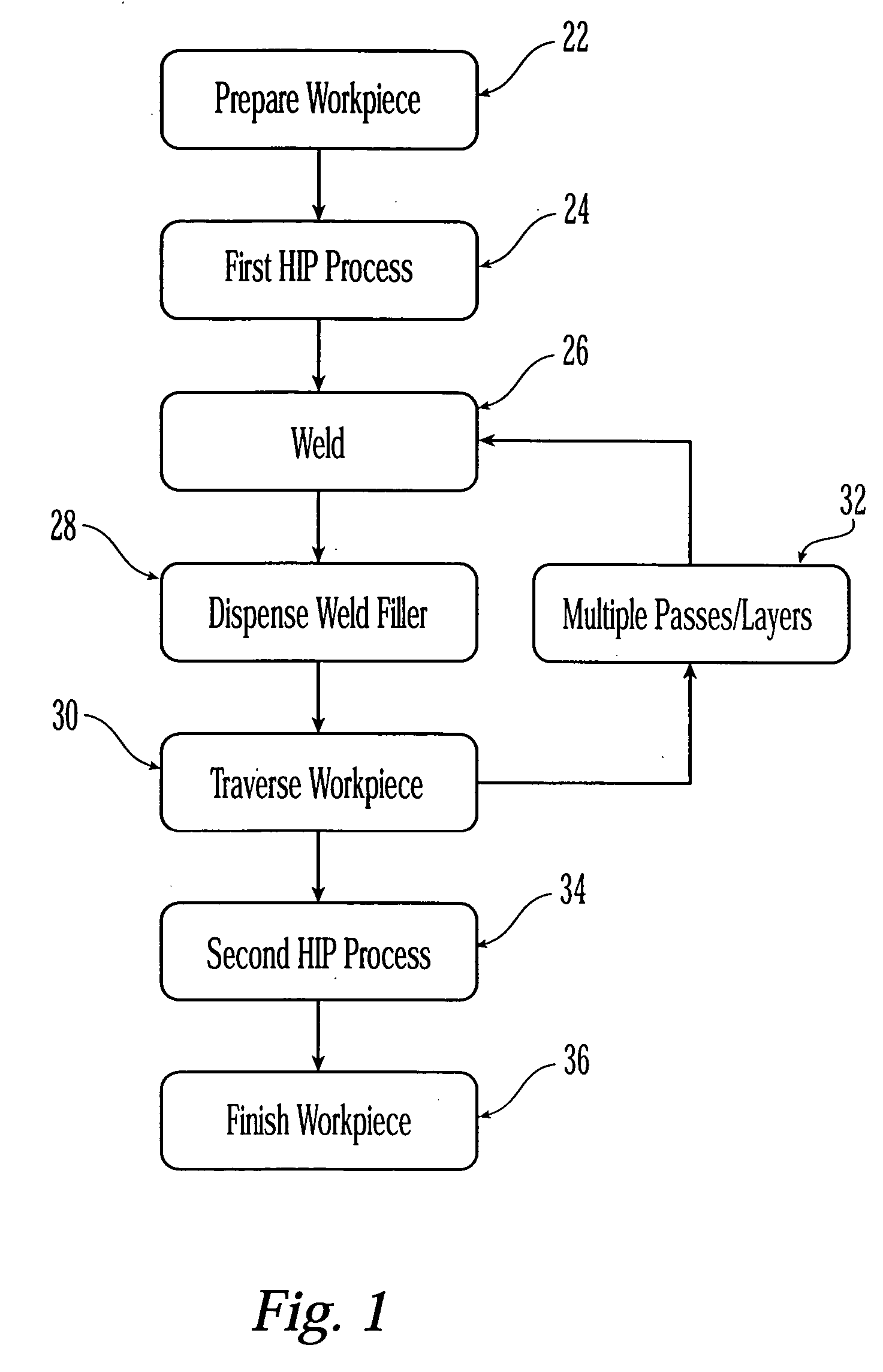
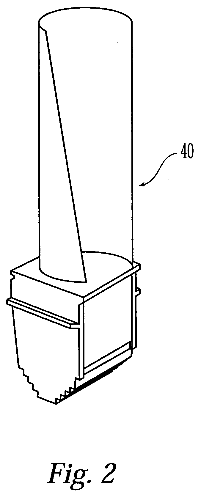
[0023]FIG. 1 is a flow chart of an embodiment of the method of the invention. In the step 22, a workpiece, such as a turbine blade, a turbine nozzle, or other metallic component that has been removed from service, is initially prepared for its repair. This prepare workpiece step 22 may include the stripping of any protective coatings from the workpiece, which is commonly accomplished with chemical stripping solutions. The prepare workpiece step 22 further includes preparing the specific areas of the workpiece that are to be repaired by conventional methods such as machining and grinding.

[0024] In the step 24, the workpiece is pre-conditioned for welding by subjecting it to a first hot isostatic process (HIP). Hot isostatic processing can be described as an idealized hot pressing or forging operation, or as high-pressure heat treatment. The basic HIP process subjects a workpiece to a combination of elevated temperatures and isostatic gas pressures (usually inert). Processing is usua...


PUM

PropertyMeasurementUnit
metallicaaaaaaaaaa
mechanical strengthaaaaaaaaaa
temperaturesaaaaaaaaaa

Abstract

A method of repairing a metallic component, such as a superalloy turbine blade or turbine nozzle, includes the step of preparing the component by stripping the protective coatings from the component. The component is then pre-conditioned for welding by a first hot isostatic process. Once the conditioning sequence is complete, the component is welded using any of a number of welding techniques and by adding weld fillers to the weld area. After the welding step, the component is sealed by a second hot isostatic process treatment performed at conditions similar to the first hot isostatic process. The component is finally prepared for re-entry into service.

Description

[0001] This application is a continuation-in-part of U.S. application Ser. No. 09 / 487,931 filed Jan. 20, 2000, now U.S. Pat. No. 6,364,971, which is incorporated by reference.BRIEF DESCRIPTION OF THE INVENTION [0002] The present invention relates to a method of repairing metallic components, and in particular to a method of repairing superalloy turbine blades and nozzles. BACKGROUND OF THE INVENTION [0003] Over the years, superalloy materials have been developed to provide mechanical strength to turbine blades (or “buckets”) and nozzles (or “vanes”) operating at high temperatures. Most modern high temperature superalloy articles such as nickel-based, precipitation strengthened superalloys are complex alloys at the cutting edge of high temperature metallurgy, and no other class of alloys can match their high temperature strength. This strength makes these alloys very useful in high-temperature high-strength requiring applications, such as turbine components. [0004] These components a...

Claims


Application Information

Patent Timeline
Patent Type & Authority Applications(United States)
IPC IPC(8): B23K20/00B23K20/02B23K26/34B23K26/42B23P6/00F01D5/00
CPCB23K9/00C22F1/10B23K10/00B23K15/00B23K20/002B23K20/021B23K26/206B23K26/421B23K2201/001B23P6/007F01D5/005F05D2230/30F05D2230/232B23K26/3213B23K26/345B23K9/044B23K26/32B23K26/342B23K26/60B23K2101/001B23K2103/18B23K2103/26
Inventor PETERSON, ARTIE GENE JR.GANDY, DAVID WAYNEFREDERICK, GREGORY J.STOVER, JAN T.VISWANATHAN, RAMASWAMY
Owner ELECTRIC POWER RES INST INC
Why Eureka
Try Eureka