

Detecting device for vehicle-mounted ATP equipment cabinet
A technology for automatic train protection and detection equipment, which is applied to locomotives, railway signals and safety, etc., can solve the problems of unsuitable 200T vehicle-mounted cabinets, no wireless functions, and inability to LKJ, etc., to achieve controllability, low cost, and reduced effect of space
- Summary
- Abstract
- Description
- Claims
- Application Information
AI Technical Summary
Problems solved by technology
Method used
Image

Examples
Embodiment 1
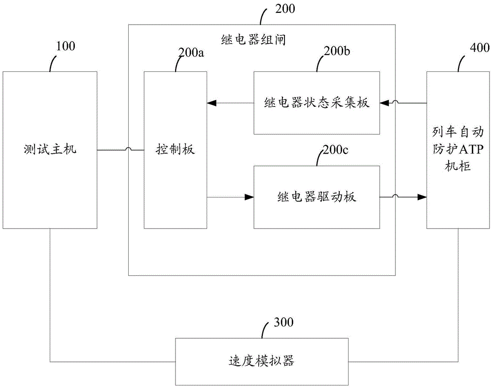
[0059] see figure 1 , which is a schematic diagram of Embodiment 1 of the vehicle-mounted train automatic protection cabinet detection equipment provided by the present invention.
[0060] The vehicle-mounted train automatic protection cabinet detection equipment provided in this embodiment includes: a test host 100, a relay group gate 200 and a speed simulator 300;
[0061] The relay group gate 200 includes a control board 200a, a relay state acquisition board 200b and a relay driver board 200c;
[0062] The test host 100 is configured to send a relay drive signal to the relay drive board 200c;
[0063] It should be noted that the test host 100 in this embodiment adopts a plug-in card host, which can be conveniently expanded with multifunction vehicle bus (MVB, Multifunction Vehicle Bus) bus, serial interface and other expansion boards.
[0064] The relay drive board 200c is used to convert the relay drive signal into an analog signal and send it to the train automatic prot...
Embodiment 2
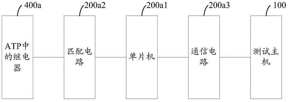
[0074] see figure 2 , which is a schematic diagram of the control board in the relay group gate of the vehicle-mounted train automatic protection cabinet detection equipment provided by the present invention.
[0075] The control board in the relay group gate provided in this embodiment includes: a single-chip microcomputer 200a1, a matching circuit 200a2 and a communication circuit 200a3;
[0076] The single-chip microcomputer 200a1 is used to control the communication circuit 200a3 to realize data interaction with the test host 100;
[0077] It should be noted that the single-chip microcomputer 200a1 is the core device of the control board, and realizes the control of the entire control board.
[0078] The single-chip microcomputer 200a1 is connected to the test host 100 through the communication circuit 200a3.
[0079] The matching circuit 200a2 is connected between the single-chip microcomputer and the ATP cabinet, and is used to realize the conversion between the signa...
Embodiment 3
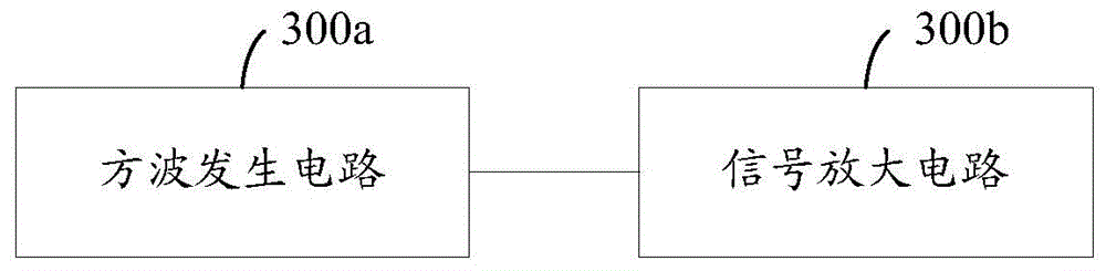
[0083] see image 3 , which is a schematic diagram of the speed simulator provided by the present invention.
[0084] The speed simulator provided in this embodiment includes: a square wave generating circuit 300a and a signal amplifying circuit 300b;
[0085] The square wave generating circuit 300a is used to generate square wave signals of different frequencies;
[0086] Since the speed signal received by the ATP cabinet is a square wave signal, it is necessary to generate a square wave signal to represent the speed signal, and square wave signals of different frequencies correspond to different speeds.
[0087] It should be noted that, the square wave generating circuit 300a can use FPGA to realize hardware circuit, and use a digital frequency synthesizer (DDS, Direct Digital Synthesizer) to realize frequency controllability.
[0088] The signal amplifying circuit 300b is configured to amplify the square wave signal and send it to the ATP cabinet.
PUM
 Abstract
Description
Claims
Application Information