Ultra-fine denier fdy spinning equipment and technology
A spinning process, ultra-fine denier technology, applied in textile equipment and its process, ultra-fine denier FDY spinning equipment and its process field, can solve the abnormal cross-section of finished silk, low success rate of components on the machine, and residence time Inconsistency and other problems, to achieve the effect of normal cross-section of finished yarn, high success rate and consistent residence time
- Summary
- Abstract
- Description
- Claims
- Application Information
AI Technical Summary
Problems solved by technology
Method used
Image
Examples
Embodiment 1
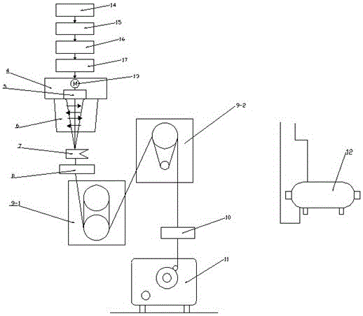
[0027] (1) Melt delivery: The melt 14 prepared by polymerization enters the melt filter 15 with a filtration accuracy of 15u to filter out the mechanical impurity particles in the melt, and the pressure is raised to 160- After 190Bar (to ensure that the pressure in front of the metering pump is ≥ 60Bar), the melt temperature is adjusted by the melt heat exchanger 17 to ensure that the melt temperature is 283-285°C, and then the melt is transported to the spinning box 4 through the melt pipeline;
[0028] (2) Metering, filtering and extrusion: Melt metering pump 13 is installed in the spinning box, and the melt is accurately metered by the metering pump. The polyester polyester melt is evenly distributed to twelve spinning assemblies 5 by twelve equal-length melt pipes, and the polyester polyester melt filter chamber 21 in the spinning assembly is filled with metal sand 22 as required by the process, and adjusted The melt enters the spinning assembly pressure, the sand amount i...
Embodiment 2
[0034] Such as figure 1 As shown, the ultra-fine denier FDY spinning equipment mainly includes melt conveying equipment and spinning equipment. The melt conveying equipment mainly includes melt filters, booster pumps, and melt heat exchangers. The spinning equipment mainly includes spinning Box, metering pump, spinning assembly, ring blowing device and biphenyl evaporator; the melt filter is connected to the inlet of the booster pump through a pipeline, and the outlet of the booster pump is connected to one end of the melt heat exchanger through a pipeline , the other end of the melt heat exchanger is connected to the metering pump and the spinning assembly in turn through the pipeline, the ring blowing device is installed under the spinning assembly, the oil nozzle oiling device is installed under the ring blowing device, and the pre-network is installed under the oil nozzle oiling device The first heat roll and the second heat roll are arranged in turn under the pre-internet...
Embodiment 3
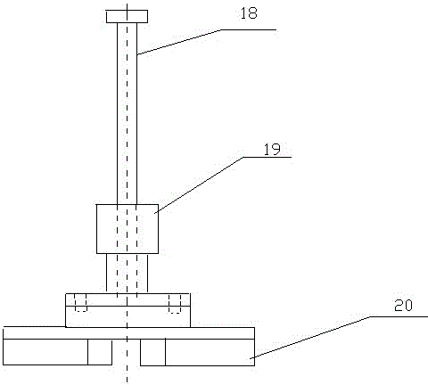
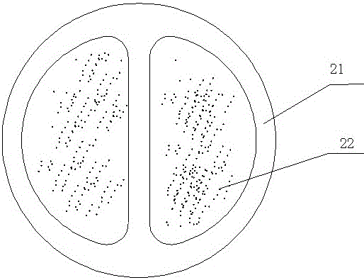
[0036] Such as figure 2 and image 3 As shown, the filter chamber is a double D-type component filter chamber 21 with metal sand 22 inside. The flat sand device is a double D type sand flat device, and the double D type sand flat device mainly includes a flat sand handle 18, a flat sand hammer 19 and a flat sand device bottom plate 20, and the flat sand handle is connected by a flat sand hammer and a flat sand device bottom plate.
[0037]If the filter sand in the filter chamber is flattened with the original D-type sand leveling device, uneven force on both sides is prone to occur. When the melt passes through the two filter chambers, the residence time is inconsistent, so that the melt is distributed unevenly on the spinneret, which will eventually lead to many floating filaments, low success rate of components on the machine, and thick and thin filaments (that is, abnormal cross-section) and wool filaments in the finished filament. , Abnormal indicators, etc.
[0038] T...
PUM
 Abstract
Description
Claims
Application Information
 - R&D
- Intellectual Property
- Life Sciences
- Materials
- Tech Scout
- Unparalleled Data Quality
- Higher Quality Content
- 60% Fewer Hallucinations
Browse by: Latest US Patents, China's latest patents, Technical Efficacy Thesaurus, Application Domain, Technology Topic, Popular Technical Reports.
© 2025 PatSnap. All rights reserved.Legal|Privacy policy|Modern Slavery Act Transparency Statement|Sitemap|About US| Contact US: help@patsnap.com


