Power electronic transformer substation

A technology of power electronics and power electronic devices, which is applied in the field of substations, can solve the problems of transformer insulation oil environment threat, substation area and land acquisition investment, and manufacturing difficulty, and meet the requirements of reducing insulation level and dynamic and thermal stability. The effect of improving the level of safe and stable operation and improving the ability of precise control

Active Publication Date: 2014-11-12
STATE GRID CORP OF CHINA +1
View PDF5 Cites 12 Cited by
  • Summary
  • Abstract
  • Description
  • Claims
  • Application Information

AI Technical Summary

Problems solved by technology

[0013] This conversion and transmission mode has the following disadvantages: it requires a lot of equipment, the volume of the transformer is large, if the oil-immersed transformer is used, there will be oil pollution problems, and at the same time, the function is relatively single, and the control is not flexible. In order to improve the power quality, it is necessary to add other unnecessary power compensation or filtering device
[0015] In the context of the power system facing these new challenges, as the most basic power facility of the power system, its shortcomings are becoming more and more obvious due to its single function. The primary equipment of the substation is bulky and difficult to manufacture. The area of ​​the substation and land acquisition The investment is huge, and the insulating oil of the transformer poses a threat

Method used


Image

  • Power electronic transformer substation
  • Power electronic transformer substation
  • Power electronic transformer substation

Examples


Embodiment Construction

[0054] Embodiments of the present invention are described in detail below, examples of which are shown in the drawings, wherein the same or similar reference numerals designate the same or similar elements or elements having the same or similar functions throughout. The embodiments described below by referring to the figures are exemplary and are intended to explain the present invention and should not be construed as limiting the present invention.

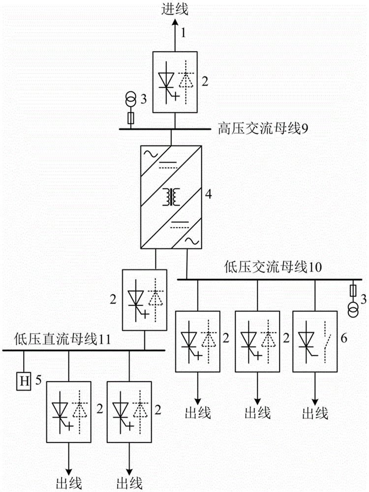
[0055] 1. In the power electronic substation provided by the present invention, the primary equipment is small in size, occupies a small area, requires less investment, and the primary and secondary equipment has strong action control capability and high stability. Such as figure 1 The power electronic substation shown includes a power electronic transformer connected between the high voltage AC bus and the low voltage AC bus through solid state circuit breakers; specifically:

[0056] The high-voltage side of the power electron...


PUM


Abstract

The invention provides a power electronic transformer substation. The high voltage side of the power electronic transformer substation is directly connected into a high voltage alternating current bus; one end of the low voltage side of the power electronic transformer substation is directly connected into a low voltage alternating current bus, the other end of the low voltage side of the power electronic transformer substation is directly connected into a low voltage direct current bus through a solid breaker; the high voltage alternating current bus comprises an alternating current inlet wire with a solid breaker; the low voltage alternating current bus comprises alternating current outlet wires provided with a solid breaker and a combination switch respectively; the low voltage direct current bus comprises a direct current outlet wire with a solid breaker; a control system of the transformer substation comprises a transformer substation dispatching layer, an inner-device coordination protecting layer and a single device control protecting layer. Compared with the prior art, the power electronic transformer substation has the advantages that rapid isolation of faults is achieved, the accurate control capability of power grids is improved, and the safe and stable operation level of the power grids is improved; meanwhile, an existing structure mode of the transformer substation is changed, the sizes of main devices are reduced, allocation of the main devices is simplified, the floor area is substantially reduced, and the good expandability is achieved.

Description

technical field [0001] The invention relates to a substation, in particular to a substation based on power electronics technology. Background technique [0002] A substation is a power facility in a power system that transforms voltage levels, receives and distributes electric energy, controls power flow, and adjusts voltage. It connects power grids at all levels of voltage through power transformers. Substations include power transformers, switchgear for opening and closing circuits, busbars for collecting current, transformers for measurement and control, instruments, relay protection devices, lightning protection devices, dispatching communication devices, and reactive power compensation equipment. [0003] Conventional substations include primary and secondary equipment. For primary equipment, single-phase or three-phase electromagnetic power transformers are generally used for voltage level conversion; electrical-mechanical circuit breakers are used to close or disconn...

Claims


Application Information

Patent Timeline
IPC IPC(8): H02B7/06H02B1/04
Inventor 戴朝波
Owner STATE GRID CORP OF CHINA
Why Eureka
Try Eureka