Biomass cyclone pyrolysis-suspension combustion composite gasification device and gasification method thereof

A technology of suspension combustion and gasification device, which can be used in granular/powder fuel gasification, manufacture of combustible gas, petroleum industry, etc., and can solve the problem of low carbon conversion rate

Active Publication Date: 2014-11-19
HARBIN INST OF TECH
View PDF7 Cites 12 Cited by
  • Summary
  • Abstract
  • Description
  • Claims
  • Application Information

AI Technical Summary

Problems solved by technology

[0004] The purpose of the present invention is to solve the problem of low carbon conversion rate caused by gas-solid separation during the operation of the existing cyclone gasifier, and to provide a biomass cyclone pyrolysis-suspension combustion composite gasification device and its gasification method

Method used


Image

  • Biomass cyclone pyrolysis-suspension combustion composite gasification device and gasification method thereof
  • Biomass cyclone pyrolysis-suspension combustion composite gasification device and gasification method thereof
  • Biomass cyclone pyrolysis-suspension combustion composite gasification device and gasification method thereof

Examples


specific Embodiment approach 1

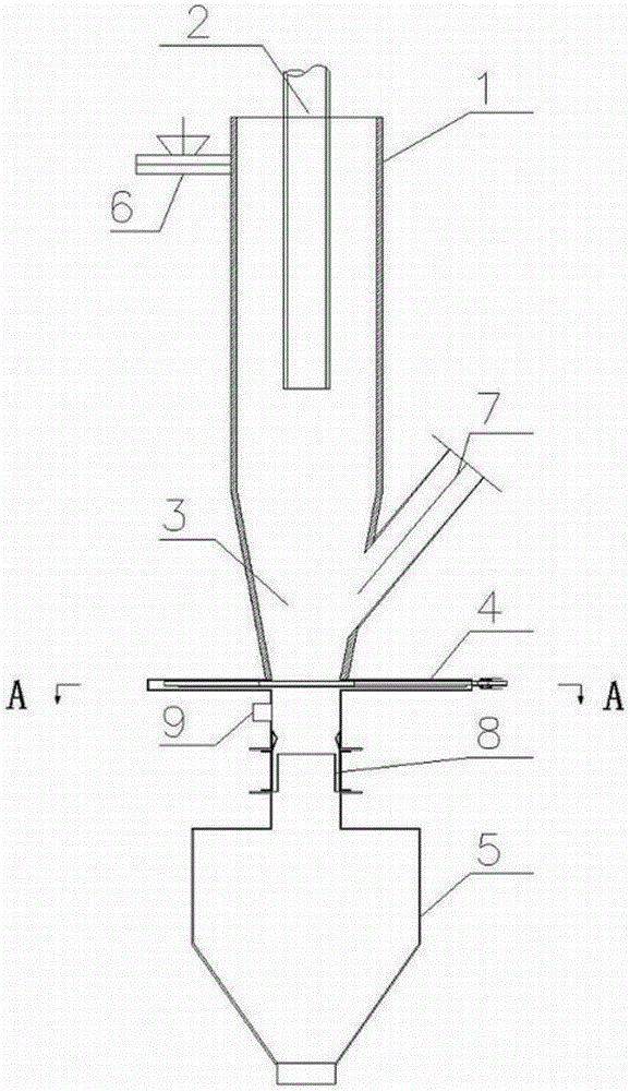
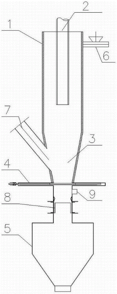
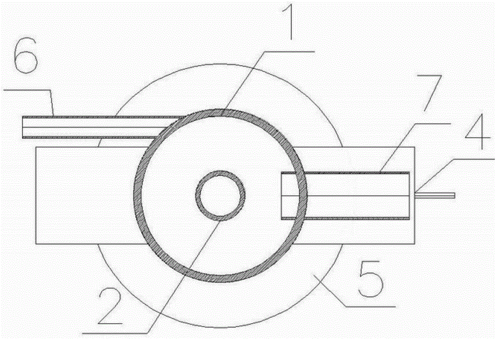
[0021] The composition of the biomass cyclone pyrolysis-suspension combustion composite gasification device in this embodiment includes: a cyclone pyrolysis chamber 1, a central exhaust pipe 2 coaxially suspended in the cyclone pyrolysis chamber 1, and an inner wall of the cyclone pyrolysis chamber 1 The lower port is coaxially connected with the upper port of the suspension combustion chamber 3, the lower end of the suspension combustion chamber 3 is fixedly connected to the switching grate 4, the lower part of the switching grate 4 is connected to the air ring 8, the lower part of the air ring 8 is fixedly connected to the ash hopper 5, and the switching grate 4 An ignition hole 9 is set between the wind ring 8; the upper part of the cyclone pyrolysis chamber 1 is plugged with one or more biomass fuel feeding pipes 6 along the tangential direction of its outer surface; the lower part of the suspension combustion chamber 3 is plugged with ignition fuel feeding Tube 7. The air...

specific Embodiment approach 2

[0023] The difference between this embodiment and specific embodiment one is:

[0024] In the biomass cyclone pyrolysis-suspension combustion composite gasification device, the switching grate 4 has a blanking gear and a gap grate, and the blanking gear and the gap grate work together with the suspension combustion chamber 3 Concentric axis setting.

specific Embodiment approach 3

[0025] The difference between this embodiment and specific embodiment 1 or 2 is: the biomass cyclone pyrolysis-suspension combustion composite gasification device, the biomass fuel feeding pipe 6 is cylindrical, and the biomass fuel feeding pipe 6 is horizontal The directions are evenly arranged on the outer wall of the cyclone pyrolysis chamber 1, and are arranged in the needle direction at the same time.


PUM


Abstract

The invention relates to a biomass cyclone pyrolysis-suspension combustion composite gasification device and a gasification method thereof. An existing cyclone gasification furnace has the defects of low biomass fuel conversion rate and low biomass gasification fuel gas heat value. The device provided by the invention has the following components: a central exhaust pipe (2) is concentrically suspended in a cyclone pyrolysis chamber (1); the cyclone pyrolysis chamber (1), a suspension combustion chamber (3), a switch grate (4), an air ring (8) and an ash hopper (5) are connected sequentially; an ignition hole (9) is arranged between the switch grate (4) and the air ring (8). A set of biomass fuel feeding pipes (6) is inserted on a tangential direction on the upper part of the cyclone pyrolysis chamber (1); an ignition fuel feeding pipe (7) is inserted on the lower part of the suspension combustion chamber (3). The gasification method comprises the following steps: a biomass fuel is sprayed into the cyclone pyrolysis chamber (1) along a tangential direction, and rotates downwards, such that a pyrolysis reaction is carried out; biomass coke particles in a pyrolysis reaction product enter the suspension combustion chamber (3), and is subjected to a combustion reaction with a main air flow from the air ring (8); and produced carbon dioxide moves upwards and is subjected to a reduction reaction with the biomass coke particles moving downwards from the suspension combustion chamber (3). The technical scheme provided by the invention is applied to the biomass gasification device and method.

Description

technical field [0001] The invention relates to a biomass cyclone pyrolysis-suspension combustion composite gasification device and a gasification method thereof. Background technique [0002] Biomass gasification is an effective way to reduce and recycle agricultural waste. Through gasification, transforming agricultural and forestry waste into clean, high-grade, and convenient biomass gas can not only improve the efficiency of resource utilization, but also have practical significance for adjusting the energy structure and reducing pollutant emissions. Air gasification is the simplest and most economical biomass gasification technology. However, because the biomass gas contains too much nitrogen, the calorific value of the gas is reduced, thus affecting the use of biomass gas. At present, the conventional method to increase the calorific value of biomass gas is to use oxygen-enriched or oxygen-enriched-water vapor instead of air as the gasification medium, but the cost i...

Claims


Application Information

Patent Timeline
Patent Type & Authority Applications(China)
IPC IPC(8): C10J3/60C10J3/66C10J3/48C10J3/50C10J3/72
Inventor 孙绍增赵义军周欣伟车宏伟栾积毅吴江全
Owner HARBIN INST OF TECH
Why Eureka
Try Eureka