Reducing furnace, and technology for directly reducing coal-containing pellets through preheating outside coal base

A reduction furnace and process technology, applied in the field of reduction furnace and coal-based external preheating coal-containing pellets direct reduction process

Inactive Publication Date: 2013-10-16
WISDRI ENG & RES INC LTD
View PDF4 Cites 7 Cited by
  • Summary
  • Abstract
  • Description
  • Claims
  • Application Information

AI Technical Summary

Problems solved by technology

The rotary hearth furnace has achieved industrial production in the treatment of dust containing Fe, Zn, Cr, and Ni in iron and steel plants. The disadvantage is that the sponge iron (DRI) has high gangue and sulfur content, which leads to an increase in the amount of steelmaking slag in the electric furnace and electrode consumption. Difficult to be directly used in the production of direct reduced iron for steelmaking
Due to the strict requirements on raw materials and fuels, the high investment and operating costs per unit capacity, the difficulty in stable operation, and the small production scale (maximum 150,000 t / year), it is difficult to become the main process for the development of direct reduced iron in my country

Method used


Image

  • Reducing furnace, and technology for directly reducing coal-containing pellets through preheating outside coal base
  • Reducing furnace, and technology for directly reducing coal-containing pellets through preheating outside coal base
  • Reducing furnace, and technology for directly reducing coal-containing pellets through preheating outside coal base

Examples


Embodiment 1

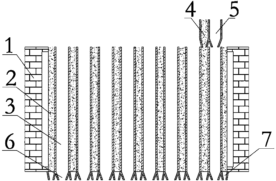
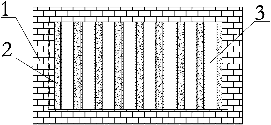
[0035] Such as Figure 1 to Figure 2 As shown, it is the reduction furnace provided by Embodiment 1 of the present invention, which includes a furnace wall 1 , a plurality of reduction tanks 3 , and a plurality of combustion tanks 2 . A plurality of reduction tanks 3 and a plurality of combustion tanks 2 are arranged alternately. The top end of each reduction tank 3 is connected with a raw material feeding device 5 , and the bottom end of each reduction tank 3 is provided with a discharge port 6 . The top of each combustion pot 2 is connected with a fuel feeding device 4 , and the bottom end of each combustion pot 2 is provided with an ash outlet 7 . The number of reduction tanks and combustion tanks can be set according to the annual production requirements.

[0036] In this embodiment, the cross-sections of each reduction tank 3 and each combustion tank 2 are quadrangular, and multiple reduction tanks 3 and multiple combustion tanks 2 are arranged alternately along the hor...

Embodiment 2

[0048] Such as Figure 4 with Figure 5 As shown, it is the reduction furnace provided in Embodiment 2 of the present invention, which is roughly the same as Embodiment 1, except that the cross sections of reduction tank 3 and combustion tank 2 are both ring-shaped, and multiple reduction tanks 3 and multiple combustion tanks Tanks 2 are concentrically arranged alternately. Feeding adopts the way of feeding tank and distribution chute, adding coal and pellets in batches.


PUM


Abstract

The invention provides a reducing furnace. The reducing furnace comprises a furnace wall, at least one reducing tank and at least one combustion tank, and the at least one reducing tank and the at least one combustion tank are alternately arranged. The top of each reducing tank is connected with a raw material feeding device, and the bottom of each reducing tank is provided with a material outlet. The top of each combustion tank is connected with a fuel feeding device, and the bottom of each combustion tank is provided with an ash outlet. The invention also provides a technology for directly heating coal-containing pellets through preheating outside a coal base. The technology comprises the following steps: 1, mixing and pelletizing an iron-containing raw material, coal dust and a binder to obtain coal pellets; and 2, providing the reducing furnace, adding the pellets to the reducing tank(s) through the raw material feeding device(s), adding fire coal to the combustion tank(s) through the fuel feeding device(s), allowing the pellets and the fire coal to independently move from top to bottom, heating and reducing the pellets to form spongy iron, and discharging the spongy iron. The reducing furnace and the reducing technology have the advantages of high shaft furnace productivity, adoption of non-coking coal as a reducing agent in coal base reduction, adoption of cheap coal as a heat source, and production of the direct reduction iron for steel making.

Description

technical field [0001] The invention belongs to the ironmaking field of the metallurgical industry, is a non-blast furnace ironmaking method, and particularly relates to a reduction furnace and a coal-based external preheating coal-containing pellet direct reduction process. Background technique [0002] Direct reduced iron (DRI), also known as sponge iron, is formed by reducing iron ore, iron concentrate or iron-containing raw materials with natural gas or non-coking coal as a reducing agent. Depending on the reducing agent, the chemical composition of the produced DRI is also different. As smelting steel types have stricter requirements on residual elements, especially steel products such as nuclear power, hydrogenation, and power stations, the use of ordinary returned scrap steel and purchased scrap steel for smelting can no longer meet the product’s requirements for residual elements. Due to its very low content of impurity elements, direct reduced iron is often used to...

Claims


Application Information

Patent Timeline
Patent Type & Authority Applications(China)
IPC IPC(8): C21B13/00
Inventor 李菊艳唐恩范小刚周强喻道明秦涔王小伟
Owner WISDRI ENG & RES INC LTD
Why Eureka
Try Eureka