Ultra wide band plasma filter provided with artificial surface

A plasma filter, artificial surface technology, applied in waveguide-type devices, electrical components, circuits, etc., can solve problems such as the inability to achieve efficient conversion functions with coaxial waveguides

Inactive Publication Date: 2014-11-19
NANJING UNIV OF AERONAUTICS & ASTRONAUTICS
View PDF10 Cites 17 Cited by
  • Summary
  • Abstract
  • Description
  • Claims
  • Application Information

AI Technical Summary

Problems solved by technology

[0005] Technical problem: The technical problem to be solved by the present invention is to provide a simple and symmetrical structure, compact size, and easy A new type of coaxial waveguide to cylindrical plasmonic waveguide converter with good performance, used in conjunction with traditional microwave transmission lines, can be used as a new type of broadband plasmonic filter on the basis of realizing efficient and broadband conversion from space guided waves to SSPPs. Provide a new idea and solution for the design and application of filters

Method used


Image

  • Ultra wide band plasma filter provided with artificial surface
  • Ultra wide band plasma filter provided with artificial surface
  • Ultra wide band plasma filter provided with artificial surface

Examples


Embodiment 1

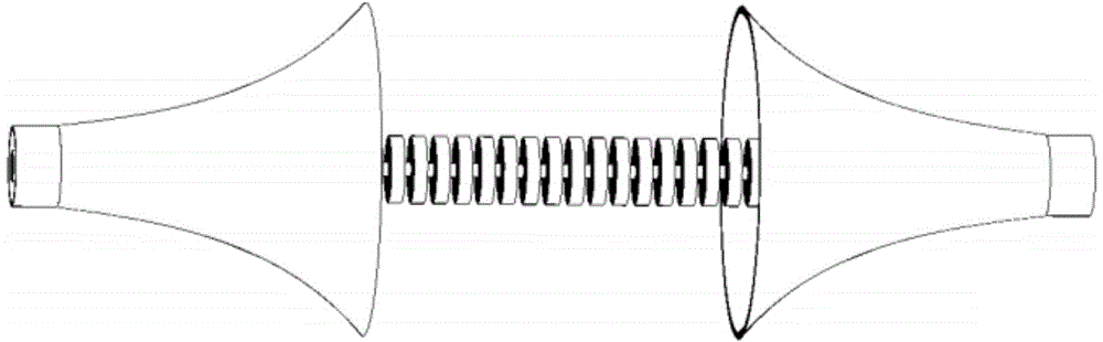
[0025] As shown in Figure 2(a), the filter is composed of coaxial waveguides symmetrical on the left and right sides, a transition waveguide from the coaxial waveguide to a cylindrical plasmonic waveguide, and a cylindrical plasmonic waveguide with a constant period in the middle. The transition waveguide includes an inner conductor and an outer conductor transition. The inner conductor transition is realized by a periodic annular groove array whose radius and depth change simultaneously, and the outer conductor transition is realized by a horn antenna whose opening gradually changes with the curve; the cylindrical plasmonic waveguide is realized by a radius and a It consists of an array of periodic annular grooves with a constant depth. The structural size parameters of the transition waveguide and the cylindrical plasmonic waveguide are adjusted according to the type and size of the coaxial waveguide, and match the parameters of the coaxial waveguide (such as waveguide type, ...

Embodiment 2

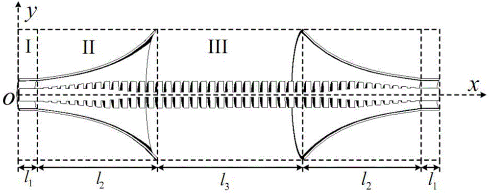
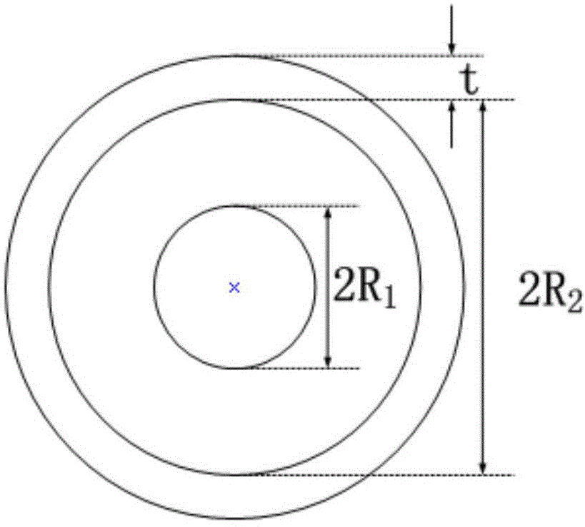
[0027] Taking the coaxial waveguide as shown in Figure 2(b) as an example, the region I is a coaxial waveguide with symmetrical left and right sides, and the total length of a single waveguide is l 1 = 10 mm, the outer diameter of the waveguide inner conductor is 2R 1 =7 mm, the inner diameter of the outer conductor is 2R 2 = 16 mm, wall thickness t = 1 mm. The coaxial waveguides at both ends of the converter can be used as the input / output end of the guided wave signal. When one of the coaxial waveguides is used as the input end, the other coaxial waveguide is the output end.

[0028] The symmetrical transition waveguides on the left and right sides are respectively connected to the coaxial waveguides on the same side to efficiently convert signals into SSPPs signals. As shown in Fig. 2(c), the transitional waveguide region II includes inner conductor and outer conductor transitions. The array of annular grooves for the inner conductor transition initially takes a radius f...


PUM


Abstract

The invention provides an ultra wide band plasma filter provided with an artificial surface. The ultra wide band plasma filter comprises a coaxial waveguide of which the two ends are symmetrical, a transitional waveguide from the coaxial waveguide to a cylindrical plasma waveguide, and the intermediate cylindrical plasma waveguide, wherein the transitional waveguide comprises an inner conductor transition and an outer conductor transition; the inner conductor transition is realized through a periodic ring-shaped groove array of which the radius and the depth change simultaneously; the outer conductor transition is realized through a horn antenna of which the opening changes gradually as a curve changes; the cylindrical plasma waveguide consists of the periodic ring-shaped groove array of which the radius and the depth are constant. The ultra wide band plasma filter provided by the invention has an open symmetrical structure, the compact size, the wide band, a high performance and a simple structure, is especially suitable for being used with a traditional microwave or a terahertz transmission line in a matching manner, can be used as the novel wide band plasma filter, and provides a fire-new thought and scheme for the design and the application of the filter.

Description

technical field [0001] The invention relates to a filter structure, in particular to an ultra-wideband artificial surface plasma filter structure. Background technique [0002] Surface Plasmon Polaritons (SPPs for short) is an electromagnetic wave mode caused by the interaction between light and free electrons on the metal surface. In this interaction, free electrons oscillate collectively under the irradiation of light waves with the same resonance frequency, which is confined near the interface between the metal and the medium and propagates along the surface. Because the plasma frequency of metals is generally in the ultraviolet band, and in the microwave band, electromagnetic waves are difficult to penetrate, and the metal approximately behaves as a perfect conductor (PEC). In these cases, although the metallic surface is in principle capable of propagating SPPs, its field is poorly confined within the medium. In recent years, it has been proposed to dig holes or groov...

Claims


Application Information

Patent Timeline
Patent Type & Authority Applications(China)
IPC IPC(8): H01P1/20
Inventor 李茁刘亮亮陈晨顾长青许秉正宁苹苹
Owner NANJING UNIV OF AERONAUTICS & ASTRONAUTICS
Why Eureka
Try Eureka