
Continuous ultralow temperature reaction device

A chemical reaction, ultra-low temperature technology, applied in the field of continuous ultra-low temperature reaction devices, can solve the problems of reduced yield of target products, high labor costs, low production efficiency, etc., to avoid the aggravation of side reactions, high work efficiency, increase Effect of reactive contact area

Active Publication Date: 2014-11-26
HENAN ACADEMY OF SCI CHEM RES INST CO LTD +1
View PDF4 Cites 3 Cited by
  • Summary
  • Abstract
  • Description
  • Claims
  • Application Information

AI Technical Summary

Problems solved by technology

Due to the serious back-mixing phenomenon during the reaction process, once the temperature in the kettle is higher than the reaction temperature, the side reactions will intensify, resulting in a decrease in the yield of the target product
During the reaction process, the temperature of the material close to the coil is extremely low, and the temperature of the material far away from the coil is high, and the cooling effect is poor
Since each production requires cleaning and re-feeding, the reactor needs to be repeatedly lowered from normal temperature to -80°C, resulting in low production efficiency, serious energy waste, and high labor costs.

Method used


Image

  • Continuous ultralow temperature reaction device
  • Continuous ultralow temperature reaction device

Examples


Embodiment 1

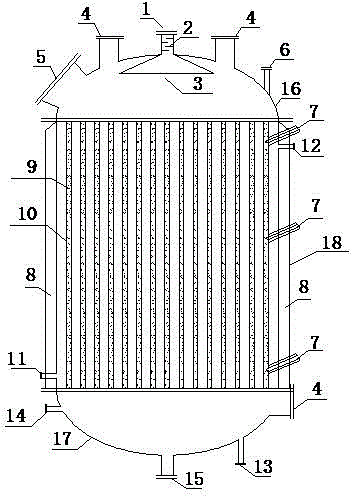
[0013] The reaction device of the present invention comprises an upper head 16 , a lower head 17 and a kettle body 18 . Its characteristics are: the upper head 16 is provided with a sight glass port 4, a manhole port 5, an inert gas inlet 6 and a feed port 1, a static tray 2 is installed in the feed port 1 pipeline, and the end of the feed port 1 pipe is A cloth distributor 3 is connected. Different liquid raw materials enter the pipeline through the feed inlet 1, are mixed on the static tray 2 in the pipeline of the feed inlet 1, and are continuously transported into the reactor after passing through the distributor 3. The kettle body 18 is composed of a series of tubes 10, an outer jacket 8, and a thermometer 7. The series of tubes 10 are vertically arranged in parallel and are equal to the length of the kettle body 18. The round holes distributed on the top are correspondingly connected, and the lower nozzle is connected correspondingly with the round holes on the bottom p...


PUM


Abstract

The invention discloses a novel continuous ultralow temperature reaction device and belongs to the field of chemical equipment. The reaction device comprises an upper seal head, a lower seal head and a kettle body, and is characterized in that a manhole orifice, a sight glass orifice, an inert gas protection pipeline and a feeding hole are formed in the upper seal head; a static tower plate is arranged in a pipeline of the feeding hole; the tail end of the pipeline of the feeding hole is connected with a distributor; the kettle body consists of tubes, an outer jacket and a thermo detector; the tubes are vertically arranged in parallel and have the same length as the kettle body; the upper orifice of each tube is correspondingly connected with round holes distributed on a bottom plate of the upper seal head, and the lower orifice of each tube is correspondingly connected with round holes distributed on a bottom plate of the lower seal head; solid catalysts or solid reaction raw materials or solid inert fillers are filled in the tubes, and a filtering net is arranged at the bottom of the tubes; liquid nitrogen is filled among the tubes; the thermo detector is positioned on one side outside the kettle body, and one end of the thermo detector is connected with the tubes; a vacuum jacket layer is arranged outside the kettle body; the sight glass orifice, a pressure gage, an inert gas outlet and a discharge opening are formed in the lower seal head. The continuous ultralow temperature reaction device can realize continuous production and avoid intensified side reactions, is low in energy consumption, high in reaction yield and stable in quality and is particularly suitable for industrial popularization and application of ultralow temperature reactions of organophosphorus, boric acid and the like.

Description

technical field [0001] The invention belongs to the field of chemical equipment, and relates to a continuous ultra-low temperature reaction device, in particular to a continuous ultra-low temperature reaction device suitable for the production of organic phosphine and boric acid products. Background technique [0002] Organic phosphines and boric acid compounds are important intermediates in the fields of pharmaceuticals, electronic chemicals, and catalysts. Most of the reactions need to be carried out at ultra-low temperatures of -80°C. At present, in industrial production, 500L low-temperature reaction kettle with stirring is mostly used for production. The structure of the reaction kettle is: a coil is added inside the kettle, and liquid nitrogen is introduced to cool down; the outside of the kettle is jacketed, and the inside of the jacket is in a vacuum state. Due to the serious back-mixing phenomenon in the reaction process, once the temperature in the kettle is higher...

Claims


Application Information

Patent Timeline
IPC IPC(8): B01J8/06
Inventor 陈辉张朋可杨振强杨瑞娜孙敏青屈凤波蒋卫鹏张银龙
Owner HENAN ACADEMY OF SCI CHEM RES INST CO LTD
Learn More