Manned submersible device observation window transparent piece fastening structure and method

A technology for manned submersibles and fastening structures, which is applied to door/window accessories, switches with braking devices, ship components, etc., and can solve stress concentration, flatness errors, and differences in the tightening degree of flange fastening bolts and other problems, to achieve the effect of increasing the load bearing capacity, improving assembly interchangeability, and avoiding assembly stress

Inactive Publication Date: 2014-11-26
YIHE TECH DEV SHANGHAI
View PDF4 Cites 7 Cited by
  • Summary
  • Abstract
  • Description
  • Claims
  • Application Information

AI Technical Summary

Problems solved by technology

[0008] 1. In the process of manufacturing and processing, there will be more or less certain defects or residual stress in the transparent part of the observation window, including grinding, polishing and annealing, etc., which will damage the internal stress balance of the transparent part itself; The process of transportation, warehousing or assembly may lead to the gradual enlargement of the defect or stress, and there will be a greater safety hazard in the future;
[0009] 2. The arc shape has higher requirements on the processing technology of transparent parts. There must be certain errors in the processing size or radian of transparent parts. Similarly, there is a flatness error in the contact surface between the submersible shell and the transparent part. The flange ring and the transparent part have flatness errors. There is also a certain degree of flatness error in the contact surface at the connection of the transparent part, and there are also differences in the tightening degree of the flange fastening bolts. The above errors will affect the fit between the transparent part and the cabin shell, resulting in difficulties in the installation of the transparent part. Or there is stress concentration after installation, and the interchangeability of transparent products is poor;
[0010] 3. During use, although there is a rubber pad between the transparent part of the observation window and the shell of the submersible, when the water pressure outside the submersible increases to a certain level, the elastic deformation of the rubber pad will reach the limit. The cushioning effect of the rubber pad will be lost and only the sealing effect will remain. At this time, the flexible contact between the transparent part and the cabin shell changes from a flexible contact to a rigid contact. In addition, there is a certain accuracy error between the transparent part and the cabin shell itself, so this Rigid contact is very unfavorable and unstable for the stressed state of transparent parts, and its own internal processing stress and installation stress will be amplified, which will further reduce the edge strength of transparent parts until cracks appear Even destroy and cause more serious safety accidents;
[0011] 4. The submersible has different pressures at different depths in the water, but the rubber pad itself cannot achieve the best sealing effect and the best cushioning effect at the same time, so how to set a suitable for the sealing and buffering effect of the rubber pad? The balance point is more difficult;
[0012] 5. When the outside of the plane transparent part is subjected to water pressure, its whole body will inevitably undergo a certain degree of deformation (concave). When the sealing range of the set gasket is not enough to cover the gap, safety accidents such as water seepage will occur around the transparent parts
[0014] However, with the progress of the times, professional technologies in all walks of life are constantly being updated, and people's demand for manned submersibles is also increasing. However, the core technology that can effectively improve the safety and convenience of submersible observation windows has not yet been resolved.
At present, there is no reasonable solution to this type of problem, and the present invention fills up the gap in this field

Method used


Image

  • Manned submersible device observation window transparent piece fastening structure and method
  • Manned submersible device observation window transparent piece fastening structure and method
  • Manned submersible device observation window transparent piece fastening structure and method

Examples


Embodiment Construction

[0069] The present invention will be further described below in conjunction with specific examples.

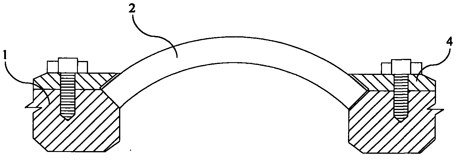
[0070] See Figure 9-11 , in the first preferred embodiment of the present invention, a kind of fastening structure of the observation window transparent part of the manned submersible of the present invention comprises the submersible shell and the observation window transparent part 2 installed in the shell; the periphery of the transparent part 2 Combined with a frame 3, the frame 3 is formed with a mounting structure that matches the housing 1, the frame 3 includes a pressing component 31 and a fastening component 32, and the pressing component 31 and the transparent part 2 press the fastening component 32 to generate prestress and then fasten Transparent part 2.

[0071] see Figure 14-15 , the fastening component 32 includes two bow-shaped arms 321 symmetrically clamped on the transparent part 2, and its material should be selected from a material with considerable str...


PUM


Abstract

A fastening structure and fastening method for the transparent part of an observation window on a manned submersible, comprising an external shell (1) and an observation window transparent part (2) arranged on the external shell (1), the peripheral edges of the observation window transparent part (2) being incorporated into a frame (3); the frame (3) comprises a compression component (31) and a fastening component (32); a pre-stressing force is generated by means of the compression component (31) fitting to the observation window transparent part (2) and compressing the fastening component (32), thereby fastening the observation window transparent part (2). The present fastening structure is very strong, and has a wide range of application.

Description

technical field [0001] The invention relates to various types of shallow-sea and deep-sea manned submersibles in the field of national defense construction, in particular to a fastening installation structure and a fastening method for a transparent part of an observation window of a manned submersible. Background technique [0002] In recent years, with the development of science and technology and the needs of national defense, scientific research and tourism, manned submersibles such as diving bells, deep-sea submarines and sightseeing submarines have been widely used. As the key structural component of the submersible, the observation window must not only have good optical performance, but also safety performance such as pressure resistance, water tightness, and air tightness are more important. Wherein the optical performance depends on the material of the transparent part of the observation window itself, and the safety performances such as pressure resistance, water t...

Claims


Application Information

Patent Timeline
Patent Type & Authority Applications(China)
IPC IPC(8): E06B3/58E06B3/04E05F5/06E06B7/16B63B19/02
CPCB63B19/00B63C11/49
Inventor 谢晓斌邹彤李震谢隽永
Owner YIHE TECH DEV SHANGHAI
Why Eureka
Try Eureka