Multiphase permanent magnet motor speed regulating system based on phase switching and speed regulating method thereof

A technology of permanent magnet motor and speed control system, applied in control system, AC motor control, electrical components and other directions, can solve the problems of poor stability, short life of permanent magnet motor, irreversible demagnetization of permanent magnet, etc. Potential, the effect of avoiding the risk of demagnetization

Inactive Publication Date: 2014-11-26
HUAZHONG UNIV OF SCI & TECH
View PDF4 Cites 30 Cited by
  • Summary
  • Abstract
  • Description
  • Claims
  • Application Information

AI Technical Summary

Problems solved by technology

[0005] Aiming at the above defects or improvement needs of the prior art, the present invention provides a multi-phase permanent magnet motor speed regulation system and its speed regulation method based on phase switching, the purpose of which is to improve the speed regulation range and flexible speed regulation of the permanent magnet motor The performance and the fault tolerance rate of the speed control system, thereby solving the technical problems of the permanent magnet motor with short life and poor stability caused by the irreversible demagnetization of the permanent magnet

Method used


Image

  • Multiphase permanent magnet motor speed regulating system based on phase switching and speed regulating method thereof
  • Multiphase permanent magnet motor speed regulating system based on phase switching and speed regulating method thereof
  • Multiphase permanent magnet motor speed regulating system based on phase switching and speed regulating method thereof

Examples


Embodiment Construction

[0021] In order to make the object, technical solution and advantages of the present invention clearer, the present invention will be further described in detail below in conjunction with the accompanying drawings and embodiments. It should be understood that the specific embodiments described here are only used to explain the present invention, not to limit the present invention. In addition, the technical features involved in the various embodiments of the present invention described below can be combined with each other as long as they do not constitute a conflict with each other.

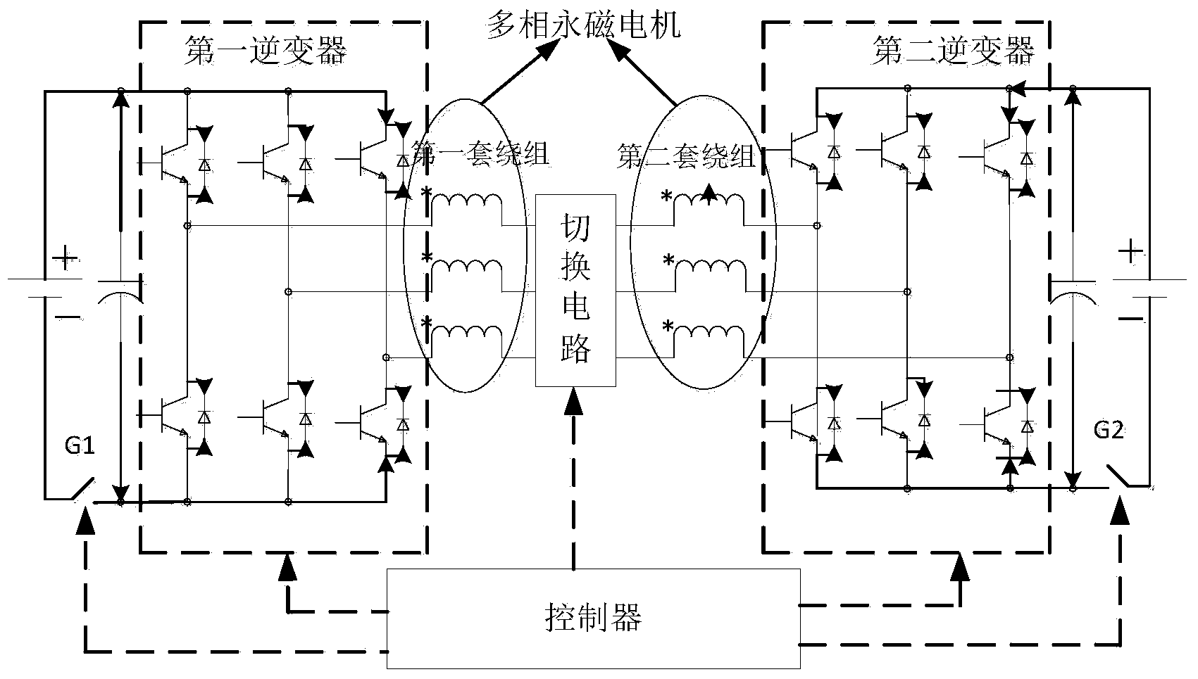
[0022] Such as figure 1 As shown, the multiphase permanent magnet motor speed control system according to the embodiment of the present invention includes: a first inverter, a second inverter, a switching circuit, a first circuit breaker G1, a second circuit breaker G2 and a multiphase permanent magnet motor . Among them, the multi-phase permanent magnet motor has two sets of three-phase windi...


PUM


Abstract

The invention discloses a multiphase permanent magnet motor speed regulating system based on phase switching and a speed regulating method thereof. The multiphase permanent magnet motor speed regulating system comprises a first inverter, a second inverter, a change-over circuit, a first circuit breaker, a second circuit breaker and a multiphase permanent magnet motor. The multiphase permanent magnet motor is of a structure including two three-phase windings. The three-phase output end of the first inverter is respectively connected with the three-phase positive end of the first winding of the motor, the three-phase negative end of the first winding is respectively connected with the three-phase positive end of the second winding of the motor, and the three-phase negative end of the second winding is respectively connected with the three-phase output end of the second inverter. The first inverter and the second inverter are respectively powered on by two independent direct current power supplies, the first circuit breaker and the second circuit breaker are respectively arranged at the low potential ends of direct current buses of the first inverter and the second inverter. The change-over circuit is used for adjusting connecting modes of the first winding and the second winding so as to adjust counter potential of the motor. The multiphase permanent magnet motor speed regulating system can widen a speed regulating range and improve speed regulating flexibility of the permanent magnet motor and the error-tolerant rate.

Description

technical field [0001] The invention belongs to the technical field of motors, and more specifically relates to a multi-phase permanent magnet motor speed control system based on phase switching and a speed control method thereof. Background technique [0002] At present, in low-voltage, high-power, high-performance, and high-reliability applications such as ship propulsion, electric locomotives, and industrial traction, motor drive systems with high torque density and quality, high efficiency, wide speed ratio, and strong fault tolerance are the research topics of people. hotspots. [0003] Research at home and abroad shows that the permanent magnet motor system has the characteristics of high torque density and high efficiency, making it gradually become the best choice for modern industrial drive systems, especially in the electric vehicle industry. However, in electric drive systems such as electric vehicles and direct-drive CNC machine tools, the operating speed range ...

Claims


Application Information

Patent Timeline
Patent Type & Authority Applications(China)
IPC IPC(8): H02P25/18H02P27/06
Inventor 杨凯魏续彪谢洪钦
Owner HUAZHONG UNIV OF SCI & TECH
Why Eureka
Try Eureka