Light-splitting device and method

A spectroscopic device and beam technology, applied in laser welding equipment, circuits, manufacturing tools, etc., can solve the problems of thermal damage to the cutting track, energy residual cutting track, etc., so as to reduce thermal damage, speed up scribing efficiency, and reduce scratches. The effect of slice line width

Active Publication Date: 2014-12-03
北京中科镭特电子有限公司
View PDF7 Cites 31 Cited by
  • Summary
  • Abstract
  • Description
  • Claims
  • Application Information

AI Technical Summary

Problems solved by technology

[0005] In the traditional laser scribing technology, no matter whether pulsed laser or continuous laser is applied, there will b...

Method used


Image

  • Light-splitting device and method
  • Light-splitting device and method
  • Light-splitting device and method

Examples


Embodiment Construction

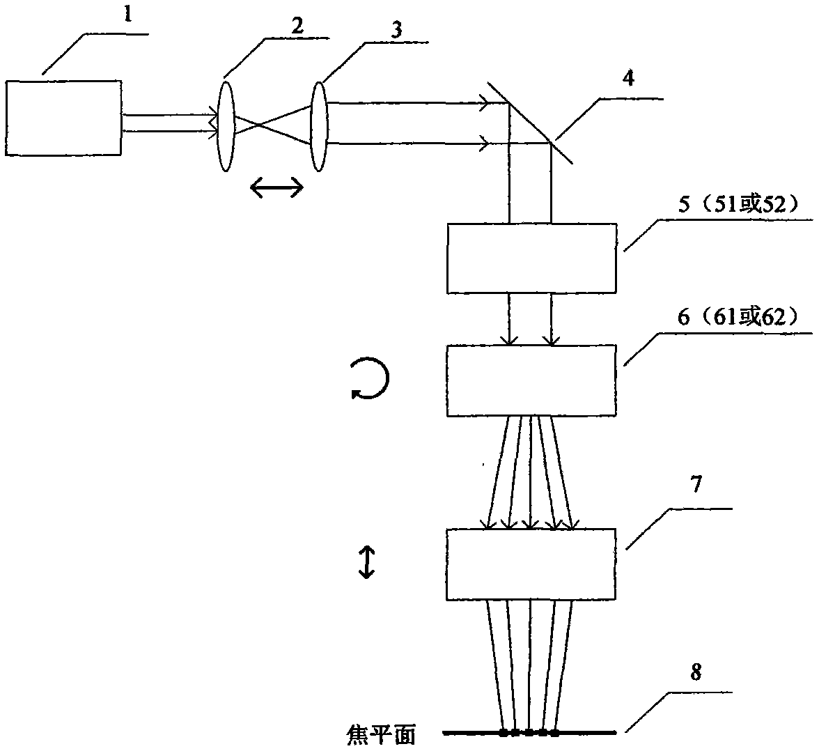
[0037] The present invention is described in detail below in conjunction with accompanying drawing:

[0038] Such as figure 1 As shown, the Gaussian beam output by the laser 1 is incident on a plane reflector or polarizer 4 after passing through a pair of lenses 2 and 3. Behind the plane reflector or polarizer 4 is a Gaussian beam shaping element 5, followed by a beam splitting element 6, and the laser After passing through the beam splitting element 6, it is incident on the focusing lens 7 and focused on the focal plane.

[0039] Laser 1 is selected according to the material characteristics and processing requirements of the workpiece to be processed. Generally, short-pulse lasers are used, and the common ones are nanosecond or picosecond lasers of 1064nm, 532nm, 355nm and 266nm. The relative distance between the lens 2 and the lens 3 can be adjusted to adjust and optimize the spot size and divergence angle characteristics of the laser output beam. The plane reflector 4 ben...


PUM


Abstract

The invention provides a light-splitting device and method. The light-splitting device comprises a pair of lenses between which the distance is adjustable, a planar reflecting mirror, a Gauss beam shaping element, a beam-splitting element and a focusing mirror, wherein the lenses are used for adjusting the light spot size and the diverging angles of Gauss beams emerged by a laser; the planar reflecting mirror is used for deflecting horizontal beams emerged by the lenses into vertical beams; the Gauss beam shaping element is used for converting light spots of the vertical beams which penetrate the Gauss beam shaping element into flat light spots with uniform energy density; the beam-splitting element is used for splitting the flat light spots into a one-dimensional or two-dimensional beam array; the focusing mirror is used for focusing the beams in the beam array to form a focus lattice.

Description

technical field [0001] The invention belongs to the technical field of laser processing, and relates to a spectroscopic device and a method thereof in laser processing equipment, and is particularly suitable for laser processing of heat-affected sensitive materials, for example, in wafer scribing, array drilling and cutting. Background technique [0002] In the recent wafer manufacturing technology, in order to improve performance, low-k materials are used, which have multiple layers of metal and some brittle materials in their structure. When the traditional diamond blade encounters these highly ductile metal layers, the diamond particles are easily wrapped by the metal and lose part of the cutting ability, which is very easy to cause fragments or broken blades. In addition to advanced ICs, in traditional diode wafer scribing, diamond knives also have many problems that cannot meet the needs of the industry: such as Gpp wafer scribing, mechanical grinding causes serious dam...

Claims


Application Information

Patent Timeline
IPC IPC(8): B23K26/067
CPCB23K26/0643B23K26/0648B23K26/0676B23K26/0732B23K26/38B23K2101/40
Inventor 李俊李纪东杨顺凯
Owner 北京中科镭特电子有限公司
Why Eureka
Try Eureka