Perpetual motion steam-driving machine

A steam engine and motive technology, applied to engine components, machines/engines, non-variable engines, etc., can solve the problems of reduced air propulsion, reduced air compression ratio, ignoring the jack principle, etc., to reduce energy consumption , The air compression ratio is increased, and the effect of improving air pollution

Inactive Publication Date: 2014-12-03
高宏亮
View PDF0 Cites 1 Cited by
  • Summary
  • Abstract
  • Description
  • Claims
  • Application Information

AI Technical Summary

Problems solved by technology

However, in the field of thermodynamics, people have ignored the application of the jack principle in the manufacture of thermal mechanical equipment, and have not fully utilized the effect of four or two jacks, resulting in low mechanical efficiency and high energy consumption of existing steam turbines
[0003] Existing steam engines or gas engines use coal or gas to generate steam or expand hot air to impact fan blades to generate mechanical energy, which belongs to the principle of windmills, but ignores the application of positive energy in the field of thermal power machinery, resulting in large energy consumption. Severe pollution and other adverse consequences; the compression cylinder of the existing compressor adopts segmental segments, so that gaps are formed between adjacent segments, causing compressed air to flow back from the gaps, resulting in reduced air propulsion, and air compression ratio reduce

Method used


Image

  • Perpetual motion steam-driving machine
  • Perpetual motion steam-driving machine
  • Perpetual motion steam-driving machine

Examples


Embodiment 1

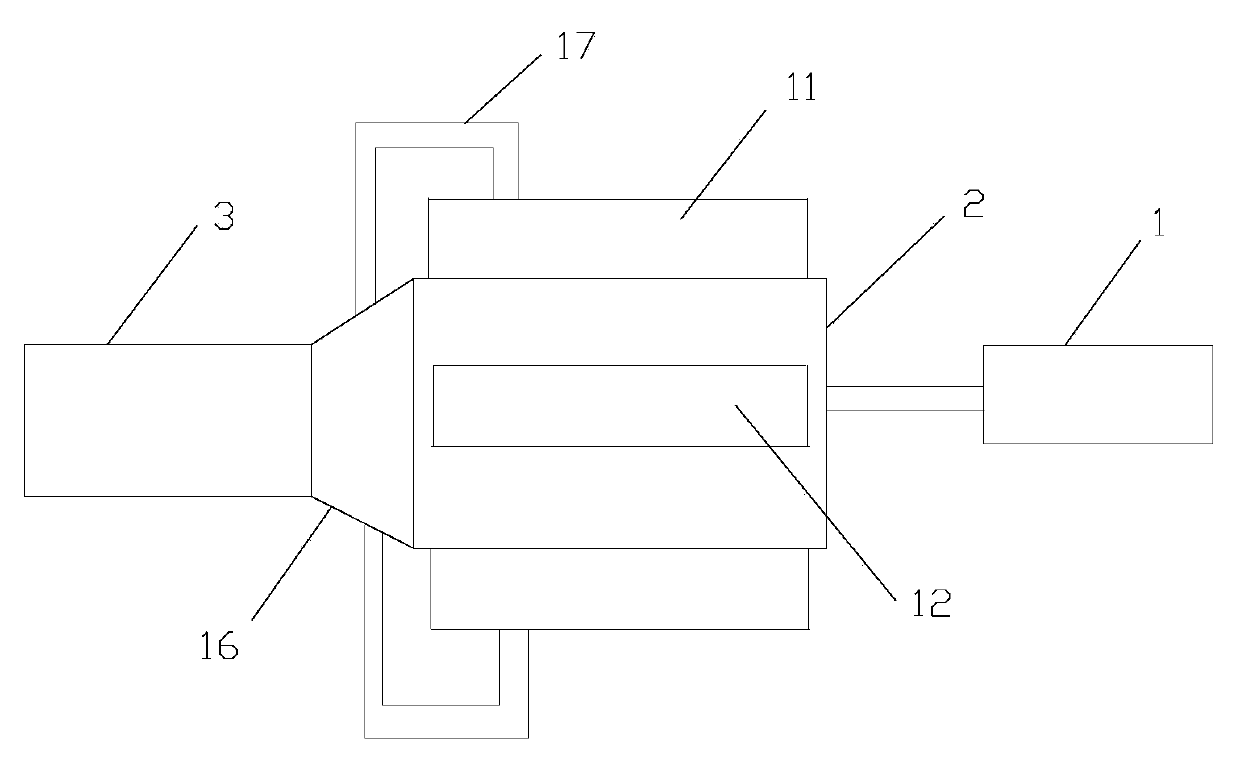
[0046] like figure 1 As shown, the perpetual motion steam motor in this embodiment includes a starter motor 1, a compressor 3 and a steam motor 2, wherein the starter motor 1 is used to assist starting of the compressor 3 and the steam motor 2, The compressor 3 is used to compress the inhaled air, and transfer the generated compressed air energy to the steam motor 2, and the steam motor is used to convert the compressed air energy into mechanical energy, and transfer the generated mechanical energy to the Compressor 3.

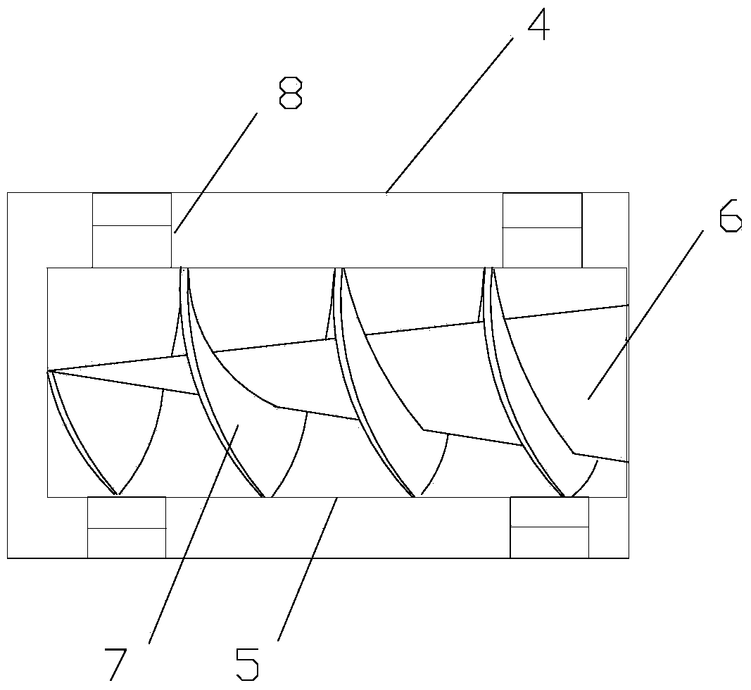
[0047] like figure 2 As shown, the compressor 3 includes a casing 4 and an air compression cylinder arranged in the casing 4, and the air compression cylinder includes an air cylinder 5 and a fan shaft arranged in the air cylinder 5, so The fan shaft includes a conical shaft 6 arranged on the central line of the gas cylinder and a number of fan 7 that surrounds the conical shaft 6 counterclockwise, and several of the fan 7 are twisted in a helical shape an...

Embodiment 2

[0076] The perpetual steam motor in this embodiment has basically the same structure as that in Embodiment 1, including a starter motor, a compressor and a steam motor, wherein the starter motor performs intermittent startup, and the compressor is used to compress the inhaled air , and transmit the generated compressed air energy to the steam motor, and the steam motor is used to convert the compressed air energy into mechanical energy, and transmit the generated mechanical energy to the compressor.

[0077] The compressor includes a casing and an air compression cylinder arranged in the casing, the air compression cylinder includes an air cylinder and a fan shaft arranged in the air cylinder, and the fan shaft includes a The tapered shaft on the central line of the gas cylinder and a number of rotary fans surrounding the tapered shaft in the counterclockwise direction, the several rotary fans are twisted in a spiral shape and evenly arranged on the tapered shaft, and The fan ...


PUM


Abstract

The invention discloses a perpetual motion steam-driving machine and is mainly designed for solving the problems in the prior art that steam engines, gas engines and air compressors are high in energy consumption, serious in pollution and low in mechanical efficiency. The perpetual motion steam-driving machine comprises a starting motor, an air compressor and a steam-driving machine, wherein the air compressor comprises a casing and an air compression cylinder arranged in the casing; the air compression cylinder comprises an air restraining cylinder and a fan rotating shaft arranged in the air restraining cylinder; the fan rotating shaft comprises a tapered shaft arranged on the axis of the air restraining cylinder and a plurality of rotating fans arranged on the tapered shaft in an encircling manner in the counter clockwise direction; the steam-driving machine at least comprises an energy storage bin, a cylinder and a steaming wheel arranged in the cylinder; the cylinder comprises a cylindrical cylinder barrel and cylinder covers arranged at two ends of the cylinder barrel; the steaming wheel comprises a cylindrical wheel body and a plurality of wheel plates uniformly distributed on the outer wall of the wheel body. The perpetual motion steam-driving machine has the advantages that the energy conservation is realized, no pollution is generated and the mechanical efficiency is high.

Description

technical field [0001] The invention relates to a mechanical power system, in particular to a perpetual motion steam engine. Background technique [0002] Perpetual motion machines are blank in the world, and any existing mechanical equipment obtains mechanical energy at the cost of energy consumption. However, in the field of thermodynamics, people have ignored the application of the jack principle in the manufacture of thermal mechanical equipment, and have not fully utilized the effect of four or two jacks, resulting in low mechanical efficiency and high energy consumption of existing steam turbines. [0003] Existing steam engines or gas engines use coal or gas to generate steam or expand hot air to impact fan blades to generate mechanical energy, which belongs to the principle of windmills, but ignores the application of positive energy in the field of thermal power machinery, resulting in large energy consumption. Severe pollution and other adverse consequences; the c...

Claims


Application Information

Patent Timeline
Patent Type & Authority Applications(China)
IPC IPC(8): F01D1/00F01D25/00
Inventor 高宏亮
Owner 高宏亮
Why Eureka
Try Eureka