
Electromagnetic shielding case based on micro metal grid and manufacturing method of electromagnetic shielding case

A technology of electromagnetic shielding cover and metal grid, applied in the direction of magnetic field/electric field shielding, electrical components, etc., can solve the problems of high cost, low processing efficiency, difficulty in large-scale consistent preparation, etc., and achieve low cost, high production efficiency, Realize the effect of mass production

Active Publication Date: 2014-12-03
SUZHOU UNIV +1
View PDF3 Cites 15 Cited by
  • Summary
  • Abstract
  • Description
  • Claims
  • Application Information

AI Technical Summary

Problems solved by technology

Considering factors such as the coaxiality of the workpiece table rotation, the control accuracy of the rotation angle, the metal etching error, and the lift-off process, it is difficult for the line width of this micro-metal grid to be less than 10 microns. In addition, the thickness of the metal layer in the evaporation process It is difficult to be higher than 1um, and its electromagnetic shielding effect is affected
In terms of processing efficiency, considering the mechanical scanning of laser direct writing, the micro-grid pattern is square, so that the direction of the grid lines is the same as the scanning direction. Since it is written line by line, when the workpiece size is large and there are many grid lines, its Processing efficiency is very low
[0007] Therefore, the above-mentioned method for preparing hemispherical metal grids has low precision and high cost, and it is difficult to prepare them consistently in large quantities.
Another disadvantage is that multiple processing on the surface of the optical element will affect the surface quality of the optical workpiece. At the same time, the preparation of the metal grid cover for other irregular shaped workpieces is more difficult.

Method used


Image

  • Electromagnetic shielding case based on micro metal grid and manufacturing method of electromagnetic shielding case
  • Electromagnetic shielding case based on micro metal grid and manufacturing method of electromagnetic shielding case
  • Electromagnetic shielding case based on micro metal grid and manufacturing method of electromagnetic shielding case

Examples


Embodiment Construction

[0047] The present invention will be described in detail below in conjunction with specific embodiments shown in the accompanying drawings. However, these embodiments do not limit the present invention, and any structural, method, or functional changes made by those skilled in the art according to these embodiments are included in the protection scope of the present invention.

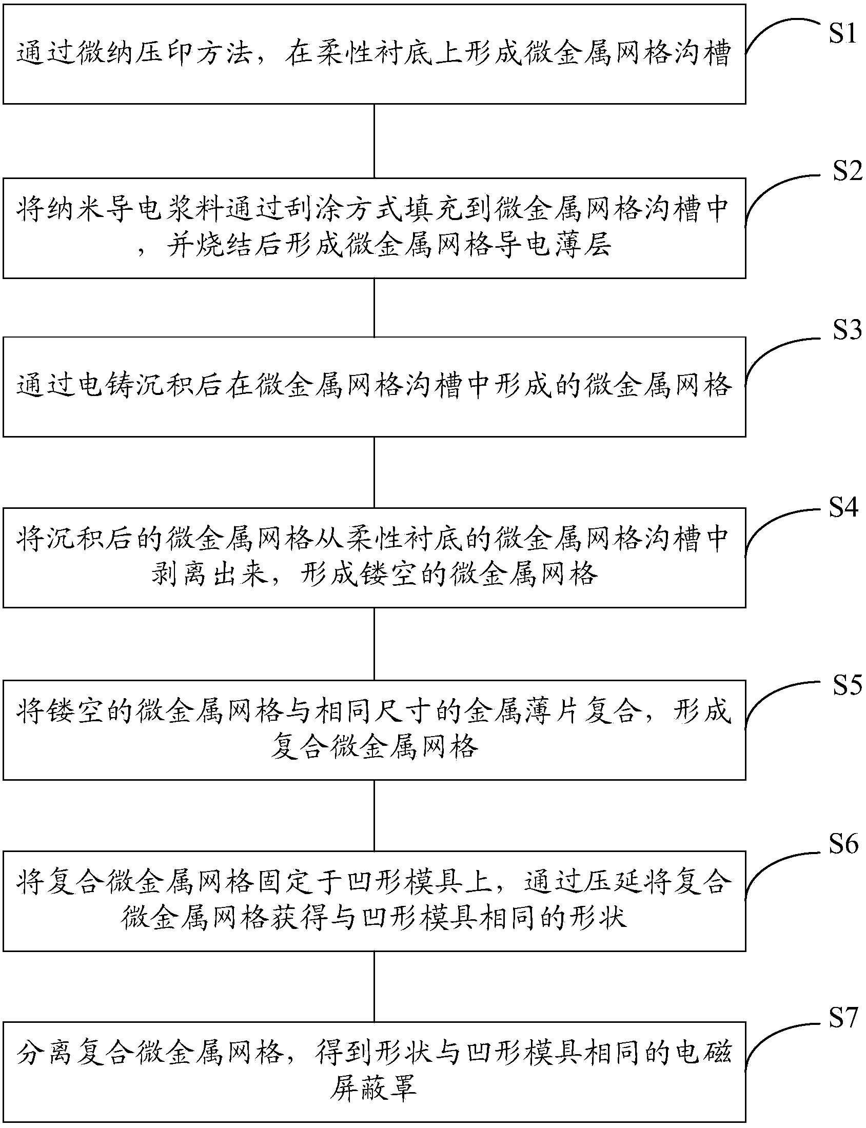
[0048] ginseng figure 1 As shown, the present invention discloses an electromagnetic shield based on micro-metal grids and a preparation method thereof, the preparation method comprising:

[0049] S1. Forming micro-metal grid grooves on the flexible substrate by micro-nano imprinting method;

[0050] S2. Filling the nano-conductive paste into the groove of the micro-metal grid by scraping, and forming a conductive thin layer of the micro-metal grid after sintering;

[0051] S3, the micro metal grid formed in the micro metal grid groove after electroforming deposition;

[0052] S4, stripping the depo...


PUM


Abstract

The invention discloses an electromagnetic shielding case based on a micro metal grid and a manufacturing method of the electromagnetic shielding case. The method comprises the following steps that micro metal grid grooves are formed in a flexible substrate according to a micro-nano impressing method; the micro metal grid grooves are filled with nanometer conductive paste in a blade coating mode, and a micro metal grid conductive thin layer is formed after sintering; the micro metal grid is formed in the micro metal grid grooves after electroforming deposition; the deposited micro metal grid is stripped out of the micro metal grid grooves of the flexible substrate, so that the hollowed-out micro metal grid is formed; the hollowed-out micro metal grid is combined with a metal sheet with the same size as the hollowed-out micro metal grid, so that the combined micro metal grid is formed; the combined micro metal grid is fixed to a concave die, and the combined micro metal grid is rolled to have the same shape as the concave die; the combined micro metal grid is separated, so that the electromagnetic shielding case having the same shape as the concave die is obtained. The electromagnetic shielding case is high in manufacturing efficiency, low in cost and capable of being manufactured on a large scale.

Description

technical field [0001] The invention relates to the technical field of electromagnetic shielding of an optical tractor, in particular to an electromagnetic shielding cover based on a metal grid and a preparation method thereof. Background technique [0002] The micro metal grid is prepared on the surface of the hemispherical optical element, which can be transparent to light wavelengths (visible light to infrared light), and has an electromagnetic shielding effect on electromagnetic wave (microwave) wavelengths. Generally, this kind of electromagnetic shielding cover of micro-metal mesh can be used for electromagnetic shielding of the hemispherical optical element of the missile seeker. [0003] In the prior art, methods for making micro-metal grids on a hemispherical surface include: [0004] 1. On the photoresist on the surface of the hemisphere, a micro-grid pattern is formed on the photoresist by laser direct writing lithography, and then a metal layer (copper, etc.) is...

Claims


Application Information

Patent Timeline
Patent Type & Authority Applications(China)
IPC IPC(8): H05K9/00
Inventor 方宗豹陈林森周小红浦东林朱鹏飞
Owner SUZHOU UNIV
Learn More