Wet-type electric precipitator and electric precipitation desulfurization device comprising same

A wet electrostatic precipitator and wet electrostatic precipitator technology, applied in combined devices, external electrostatic separators, electrode cleaning, etc., can solve the problems of affecting the dust collection effect, reducing the purification efficiency, frequent electric sparks, etc., and improve the efficiency of the dust removal system , reduce emission concentration, and save floor space

Active Publication Date: 2014-12-10
ZHEJIANG TIANLAN ENVIRONMENTAL PROTECTION TECH
View PDF8 Cites 31 Cited by
  • Summary
  • Abstract
  • Description
  • Claims
  • Application Information

AI Technical Summary

Problems solved by technology

[0006] However, the traditional wet electrostatic precipitator has the following deficiencies: 1) The distribution of the airflow between the electrodes is uneven, and there are even "dead angles", which reduces the dust collection efficiency
2) The corona intensity of traditional plate electrodes, wire electrodes, and rod electrodes is not high enough, so it is necessary to increase the voltage to obtain a high dust collection rate and prevent arc extinguishing effects, and obtain a high dust collection rate and prevent arc extinguishing effects
3) The traditional circular electrode tube has the problem that it is difficult to maintain the concentricity accurately, which makes the electric field uneven, easily causes frequent electric sparks, and affects the overall dust collection effect
4) Purified gas and flushing wastewater are discharged from the same outlet in the same direction, which may easily cause the purified gas to carry dirty wastewater, which seriously reduces the purification efficiency

Method used


Image

  • Wet-type electric precipitator and electric precipitation desulfurization device comprising same
  • Wet-type electric precipitator and electric precipitation desulfurization device comprising same
  • Wet-type electric precipitator and electric precipitation desulfurization device comprising same

Examples


Embodiment 1

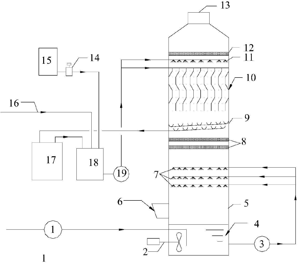
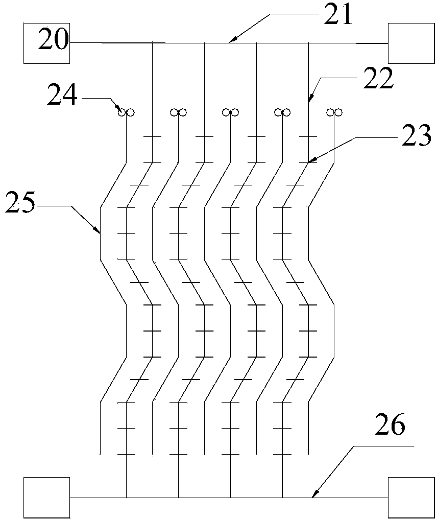
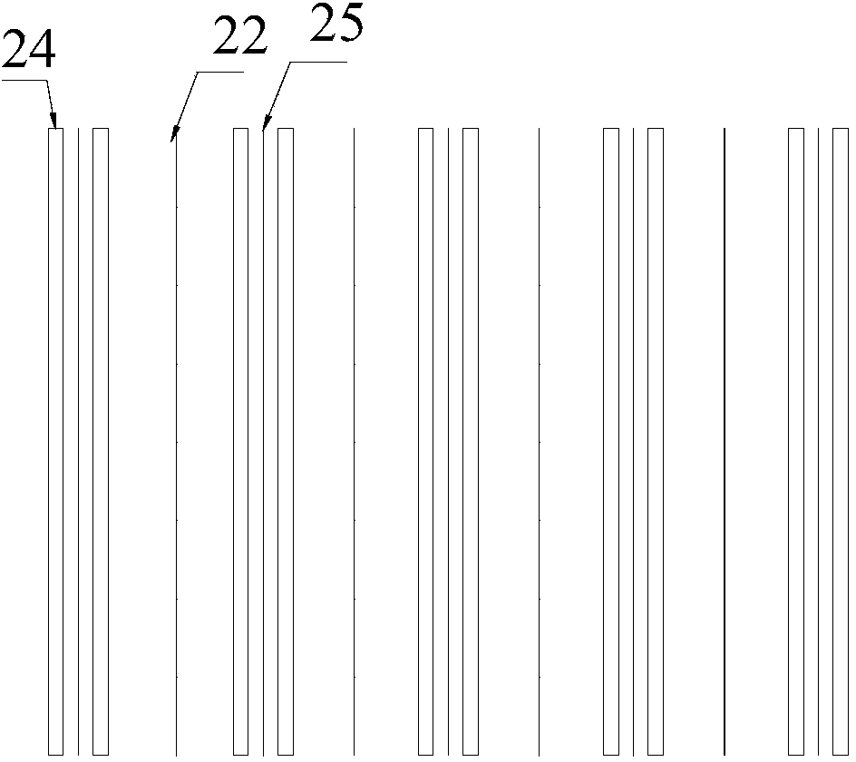
[0085] Using the above-mentioned self-designed wet electrostatic precipitator and desulfurization device, the length of the bent plate of the wet electrostatic precipitator is 8m, the distance between the two creases is 300mm, and the angle of the bend is 140°. Two adjacent bent plates The distance between them is 280mm, the length of the burrs is 25mm, the distance between adjacent burrs is 50mm, and the distance between several cathode lines between two adjacent bent plates is 250mm.

[0086] There is a gypsum slurry atomizing nozzle at the lower end of the pilot test device to simulate the water mist and dust in the flue gas. The atomized slurry enters the wet electrostatic precipitator through the blower of the fan. The water mist content and slurry dust at the inlet of the wet electrostatic precipitator are controlled and the voltage is adjusted. , to measure the removal efficiency of water mist and dust at the outlet of the wet electrostatic precipitator.

[0087]

Embodiment 2

[0089]Using the above self-designed and manufactured wet electrostatic precipitator and desulfurization device, the length of the bent plate of the wet electrostatic precipitator is 2m, the distance between the two creases is 800mm, and the angle of the bend is 170°. Two adjacent bent plates The distance between them is 400mm, the length of the burrs is 5mm, the distance between adjacent burrs is 150mm, and the distance between several cathode lines between two adjacent bent plates is 500mm.

[0090] There is a gypsum slurry atomizing nozzle at the lower end of the pilot test device to simulate the water mist and dust in the flue gas. The atomized slurry enters the wet electrostatic precipitator through the blower of the fan. The water mist content and slurry dust at the inlet of the wet electrostatic precipitator are controlled and the voltage is adjusted. , to measure the removal efficiency of water mist and dust at the outlet of the wet electrostatic precipitator.

[0091] ...

Embodiment 3

[0093] Using the above self-designed and manufactured wet electrostatic precipitator and desulfurization device, the length of the bent plate of the wet electrostatic precipitator is 4m, the distance between the two creases is 600mm, and the angle of the bend is 155°. Two adjacent bent plates The distance between them is 350mm, the length of the burrs is 10mm, the distance between adjacent burrs is 100mm, and the distance between several cathode lines between two adjacent bent plates is 400mm.

[0094] There is a gypsum slurry atomizing nozzle at the lower end of the pilot test device to simulate the water mist and dust in the flue gas. The atomized slurry enters the wet electrostatic precipitator through the blower of the fan. The water mist content and slurry dust at the inlet of the wet electrostatic precipitator are controlled and the voltage is adjusted. , to measure the removal efficiency of water mist and dust at the outlet of the wet electrostatic precipitator.

[0095...


PUM

PropertyMeasurementUnit
lengthaaaaaaaaaa
lengthaaaaaaaaaa
lengthaaaaaaaaaa

Abstract

The invention discloses a wet-type electric precipitator and an electric precipitation desulfurization device comprising the same. The wet-type electric precipitator comprises anode plates, cathode rays, two cathode ray suspension frames, an insulator chamber and a cleaning water pipe, wherein multiple bending plates which extend along the vertical direction and are arranged in parallel are used as the anode plates; the multiple cathode rays are suspended between two adjacent bending plates and are bent in tendency the same as that of the bending plates; multiple barbs are fixed on each cathode ray at intervals; the two cathode ray suspension frames are respectively positioned above and below the anode plates and are used for fixing the top ends and bottom ends of the cathode rays; the insulator chamber is used for fixing the ends of the two cathode ray suspension frames; and the cleaning water pipe is arranged above the anode plates. The wet-type electric precipitator disclosed by the invention is used in the desulfurization device, is arranged between two-stage demisting layers in a desulfurization tower and is used for performing fine dust removal on flue gas subjected to primary demisting.

Description

technical field [0001] The invention relates to the technical field of air pollution control, in particular to a wet electrostatic precipitator and an electric dust removal desulfurization device including the wet electrostatic precipitator, which are used for removing dust PM2.5 and water vapor in flue gas after desulfurization Wet electrostatic precipitator is suitable for the flue gas dust removal field of power station boilers, industrial boilers, incinerators, etc. Background technique [0002] With the continuous occurrence of environmental pollution incidents with "smog" as the main form, coal-fired power plants with dust emissions accounting for more than 70% of the total have become the target of public criticism. Although the newly promulgated "Emission Standard of Air Pollutants for Thermal Power Plants (GB13223-2011)" only controls the dust emission concentration of coal-fired power plants to 20mg / Nm 3 , the emission requirements for natural gas mentioned 5mg / Nm...

Claims


Application Information

Patent Timeline
Patent Type & Authority Applications(China)
IPC IPC(8): B03C3/16B03C3/78B01D53/78B01D53/50B01D53/96B01D50/00
Inventor 寿冬金王岳军莫建松孙华刘学炎
Owner ZHEJIANG TIANLAN ENVIRONMENTAL PROTECTION TECH
Why Eureka
Try Eureka