
A method and device for improving the efficiency of a turbine engine

A turbine engine and engine technology, applied in the fields of engines and rotors, can solve the problems of the gas turbine engine not working normally, the flow of the flowing working medium is small, and the output torque of the force arm is short, so as to improve the conversion of heat energy into mechanical work efficiency, increase the The effect of enthalpy drop and long force time

Active Publication Date: 2017-10-03
肇庆高新区伙伴汽车技术有限公司
View PDF1 Cites 0 Cited by
  • Summary
  • Abstract
  • Description
  • Claims
  • Application Information

AI Technical Summary

Problems solved by technology

When the speed of the gas turbine engine is low, its coaxially driven axial flow or centrifugal speed compressor will not be able to provide the corresponding gas pressure to the combustion chamber, so that the gas turbine engine cannot work normally
For gas turbine engines with output power below tens to hundreds of kilowatts, due to the small flow rate of the working medium, its turbine diameter is small, the moment arm is short, and the output torque is small. Increasing the speed and increasing the power will be detrimental to the transmission, etc. The above disadvantages It is the main reason why the gas turbine engine is coldly received in the field of vehicle engine applications, regardless of whether it has no complicated crank-link mechanism in structure or has technical advantages over piston internal combustion engines in other aspects

Method used


Image

  • A method and device for improving the efficiency of a turbine engine

Examples


Embodiment Construction

[0047] The present invention will be further described below.

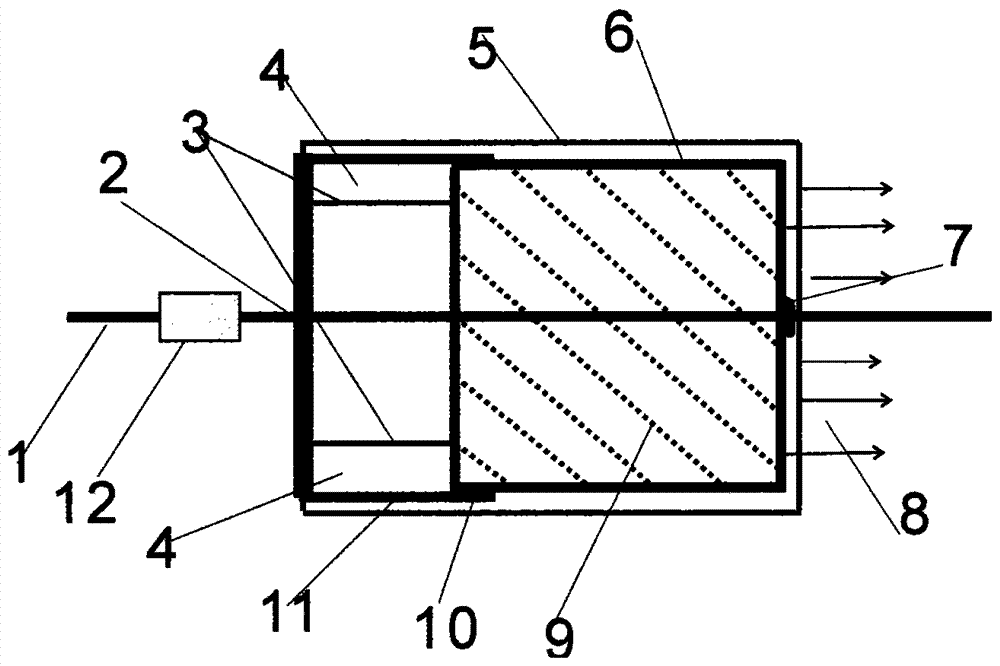
[0048] A method for improving the efficiency of a turbine engine, comprising: a method for increasing the water head of the working medium adopted by the hydraulic turbine engine, or a method for increasing the temperature and pressure of the initial state working medium adopted by the gas turbine engine, or a method for increasing the temperature and pressure of the initial state working medium adopted by the steam turbine engine , heat recovery cycle, cooling the exhaust gas method or the method of increasing the initial state working medium pressure adopted by the compressed air turbine engine, also including replacing the turbine rotor with a spiral tube rotor, and manufacturing the turbine engine into a hydraulic spiral tube rotor engine or a gas spiral tube rotor engine Or steam helical rotor engine or compressed air helical rotor engine, so that the flow direction of the flowing working medium in the helical...


PUM


Abstract

The invention provides a method and device for improving the efficiency of a turbine engine. Involving rotor, engine. Replace the turbine rotor with the helical rotor, and make the turbine engine into a hydraulic helical rotor engine, a gas helical rotor engine, a steam helical rotor engine, or a compressed air helical rotor engine, so that the flow of the working medium in the helical tube of the helical tube rotor The direction changes continuously, and the energy of the fluid working medium is converted into mechanical work and output power. Reduce the energy loss of the flowing working medium that is not related to the work process. If the reduction of working fluid flow caused by the reduction of installed power can be dealt with by reducing the number of spiral tubes of the spiral tube rotor and or the diameter of the screw tubes, the diameter of the screw tube rotor should not be reduced. The efficiency of these engines can be increased by more than 5% respectively. The gas helical rotary engine and the steam helical rotary engine can be used as conventional vehicle engines. Ships, aircraft, power generation, conventional vehicles and other devices equipped with helical rotor engines are more energy-saving and environmentally friendly.

Description

technical field [0001] The present invention relates to a rotor and an engine, and further specifically relates to a helicoidal rotor engine composed of a helicoidal rotor. Background technique [0002] A turbine is an engine that uses fluid to impinge on the rotation of the impeller to generate power. It is mainly divided into four types: gas turbine engine, steam turbine engine, water turbine engine (ie water turbine), and compressed air turbine engine. When we are not pursuing the thrust of the jet flight of the turbine engine, but the efficiency of the turbine engine converting the energy of the flowing working medium into mechanical work, the energy conversion capability of the turbine engine basically determines the efficiency of these turbine engines. The turbine engines of the prior art are widely used in civil and military fields such as power generation, aircraft, ships, and power, and play a very important role. How to improve turbine engine efficiency? Reducing...

Claims


Application Information

Patent Timeline
Patent Type & Authority Patents(China)
IPC IPC(8): F01C1/16
Inventor 罗显平
Owner 肇庆高新区伙伴汽车技术有限公司
Learn More