
Fluorescence observation method and fluorescence observation equipment

A technology of fluorescence and equipment, applied in the field of fluorescence observation equipment, which can solve the problems of destroying spatial coincidence, difficulty in manufacturing optical systems that meet expected specifications, changes, etc.

Inactive Publication Date: 2017-05-10
OLYMPUS CORP
View PDF4 Cites 0 Cited by
  • Summary
  • Abstract
  • Description
  • Claims
  • Application Information

AI Technical Summary

Problems solved by technology

[0005] (Problem 1) In the case of simultaneous observation of multiple types of fluorescent molecules, in order to simultaneously irradiate the sample with multiple types of excitation lights having different wavelengths from each other, an optical system for mixing the multiple types of excitation lights in the same path is required so that Complex optical structure;
[0006] (Problem 2) When fluorescence observation is performed using a plurality of excitation lights having different wavelengths from each other, the plurality of excitation lights to be collected on the sample surface are distorted due to chromatic aberration that occurs when they pass through optical systems located on their paths. cause their focal position to vary with their wavelength so that spatial coincidence is broken
As a result, this problem can lead to artifacts in the analysis of overlap between various biomolecules or the localization of biomolecules; and
[0007] (Problem 3) Although fluorescence observation is performed one by one for each fluorescent molecule while sequentially changing a plurality of excitation lights having different wavelengths, the process does not allow simultaneous observation of the fluorescent light emitted from the individual fluorescent molecules
[0011] (Problem 4) In order to collect and guide light in the deep ultraviolet region to fluorescent molecules, there are few optical members available, and there are many restrictions in the configuration of the optical system, and therefore, it is difficult to manufacture an optical system that satisfies desired specifications
[0012] (Question 5) Compared with visible light or infrared light, light in the deep ultraviolet region has greater light energy and causes large photodamage to living bodies
As a result, in the case where the object to be observed is a living sample such as a living cell, light in the deep ultraviolet region is not suitable as excitation light for observing fluorescence emitted from fluorescent molecules labeled on the sample

Method used


Image

  • Fluorescence observation method and fluorescence observation equipment
  • Fluorescence observation method and fluorescence observation equipment
  • Fluorescence observation method and fluorescence observation equipment

Examples


Embodiment approach

[0094] Embodiments of the present invention are explained below using the drawings.

Embodiment approach 1

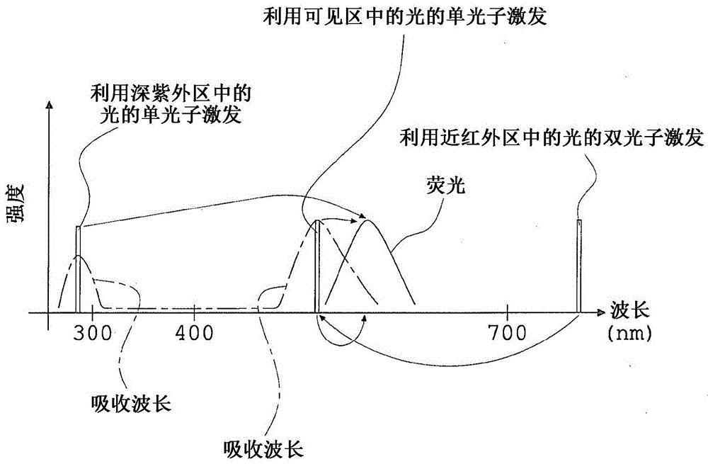
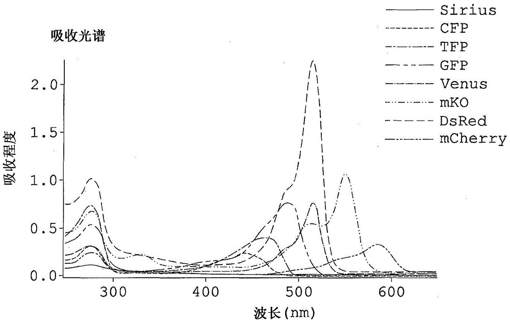
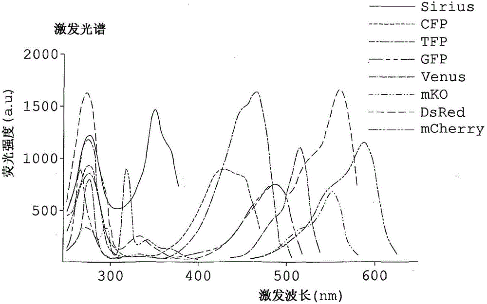
[0096] Figure 8 It is an explanatory diagram schematically showing the overall structure of a fluorescence observation apparatus used in the fluorescence observation method according to Embodiment 1 of the present invention. Figure 9 is to show the relationship between the range of excitation wavelength, the range of fluorescence wavelength emitted by each of the fluorescent proteins, and the range of fluorescence wavelength detected by each detector in the fluorescence observation method of Embodiment 1 using the fluorescence observation apparatus. Relationship graph.

[0097] Such as Figure 8 As shown, the fluorescence observation apparatus in the present embodiment is provided with a light source unit 11 , a second harmonic generation unit 12 and a unit 13 for specimen observation.

[0098] The light source unit 11 is constituted by an ultrashort pulse laser like a mode-locked laser, a variable-wavelength laser OPO, or the like.

[0099] The second harmonic generating...


PUM

PropertyMeasurementUnit
wavelengthaaaaaaaaaa
lengthaaaaaaaaaa

Abstract

A fluorescence observation method of the present invention for detecting plural types of fluorescence emitted from two or more kinds of fluorescent molecules includes: subjecting each of the two or more kinds of fluorescent molecules to multi-photon excitation by exciting light having an exciting wavelength equal to or shorter than 700 nm in a visible region, to generate fluorescence upon making use of an absorption wavelength band in a deep ultraviolet region of each of the two or more kinds of fluorescent molecules; and simultaneously detecting plural types of fluorescence generated on a shorter-wavelength side or on both of the shorter-wavelength side and a longer-wavelength side of the exciting wavelength of the exciting light.

Description

technical field [0001] The present invention relates to a fluorescence observation method of observing fluorescence emitted from fluorescent molecules such as various fluorescent proteins, and to a fluorescence observation apparatus. Background technique [0002] Using fluorescent molecules to observe biomolecules is a standard observation method in the field of medicine or life sciences. Various fluorescent molecules having different fluorescence wavelengths have been developed, and various biomolecules can be observed in combination with each other using these fluorescent molecules. [0003] Among conventional methods of observing fluorescence emitted by fluorescent molecules, for example, there is a method in which fluorescent molecules are excited by single-photon excitation using light in the visible region and fluorescence generated on the longer wavelength side of the wavelength of the excitation light is detected (Stokes shift); and a method in which fluorescent mol...

Claims


Application Information

Patent Timeline
Patent Type & Authority Patents(China)
IPC IPC(8): G01N21/64G02B21/00G01N33/58
CPCG01N21/6458G02B21/0076A61B6/037A61B6/0478A61B6/501G01N2021/6421G01N2021/6471G01N2201/068G01N2201/0697G01T1/2985
Inventor 藤田克昌永井健治齐藤健太山中真仁泷本真一
Owner OLYMPUS CORP
Learn More