Scroll compressor

A technology of scroll compressors and scroll disks, applied in the direction of rotary piston machinery, rotary piston pumps, mechanical equipment, etc., can solve the problems of reduced compression efficiency, length increase, and compression efficiency reduction, and achieve improved compression Effects of efficiency and reliability, reduction in length and diameter, and reduction in friction loss

Inactive Publication Date: 2014-12-17
LG ELECTRONICS INC
View PDF5 Cites 3 Cited by
  • Summary
  • Abstract
  • Description
  • Claims
  • Application Information

AI Technical Summary

Problems solved by technology

[0014] However, in the conventional scroll compressor as described above, a large height difference Δh occurs between the support point A where the crankshaft 23 is supported by the main frame 3 and the action point B where the crankshaft acts on the orbiting scroll. As a result, the crankshaft 23 is subjected to a large eccentric load, so that the load of the gas pressure on the bearing increases, thereby increasing the friction loss and reducing the compression efficiency
In addition, the force acting on the welding point is also increased due to the gas pressure, so there is a problem that the noise of the compressor increases and the reliability decreases.
[0015] In addition, as the crankshaft 23 receives a large eccentric load, the weight of the eccentric mass 8 provided on the crankshaft 23 increases, not only the cost rises, but also the amount of deformation of the crankshaft 23 increases, thereby reducing the compression efficiency due to friction loss. The centrifugal force of mass 8 increases, the force on the welding point also increases, and there is the problem of increased compressor noise and reduced reliability
[0016] In addition, since the shaft hole 31 for supporting the crankshaft 23 of the main frame 3 is spaced at a predetermined distance from the pocket groove 32 for inserting the bushing portion 53 of the orbiting scroll 5 so as to be able to swivel Therefore, the length of the main bearing portion 23b of the crankshaft 23 is elongated, and the crankshaft 23 is subjected to a large eccentric load 8, resulting in an increase in the size of the main frame 3. As a result, the axial length of the compressor is elongated, and the material cost is increased, thereby There is a limitation in increasing the stack height of the motor

Method used


Image

  • Scroll compressor
  • Scroll compressor
  • Scroll compressor

Examples


Embodiment Construction

[0049] Next, based on an embodiment shown in the drawings, the scroll compressor of the present invention will be described in detail.

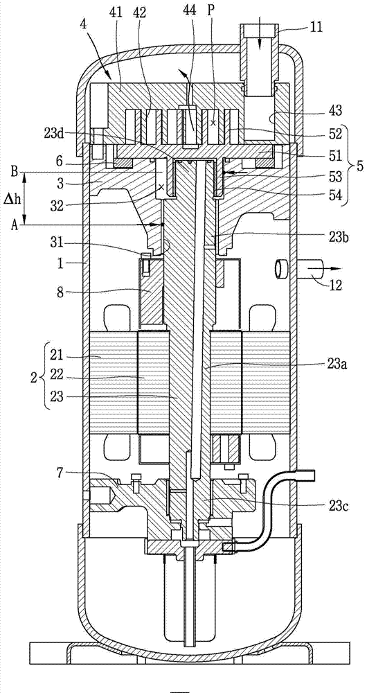
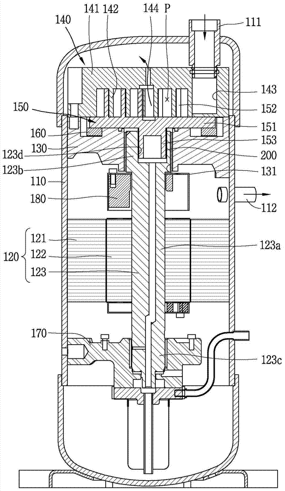
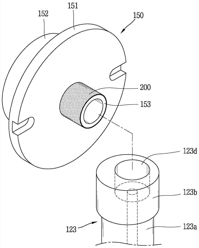
[0050] figure 2 It is a longitudinal sectional view showing an example of a scroll compressor of the present invention, image 3 will be figure 2 A perspective view showing the orbiting scroll and crankshaft of a scroll compressor separated, Figure 4 is showing figure 2 A longitudinal sectional view of the compression part of a scroll compressor, Figure 5 as well as Figure 6 is to illustrate Figure 4 The scroll compressor bushing combined with the minimum groove thickness is shown along the Figure 4 The sectional view cut by the "I-I" line of , and the disassembled sectional view of the orbiting scroll and crankshaft, Figure 7 is showing Figure 4 A top view of the contact relationship between the bushing part and the bushing coupling groove of the scroll compressor.

[0051] As shown in the figure, in the scroll compressor ...


PUM


Abstract

In a scroll compressor the present invention, a boss portion of an orbiting scroll is inserted to be coupled to a boss coupling recess of a crank shaft, and thus, friction loss of the bearing portion is reduced, enhancing compression efficiency and reliability and reducing noise and material costs Also, a bush bearing is coated to be formed on the boss portion of the orbiting scroll, a thickness of a bearing portion may be reduced. Also, since an outer circumferential surface of the bearing portion is in contact with an inner circumferential surface of the boss coupling recess, damage to the bearing portion may be prevented.

Description

technical field [0001] The present invention relates to a scroll compressor, and more particularly, to a scroll compressor in which an inclined portion is formed on a pin portion of a crankshaft. Background technique [0002] A scroll compressor is a compressor in which a fixed scroll is fixed in the inner space of a closed container, and the orbiting scroll engages with the fixed scroll to perform orbital motion, thereby Two pairs of compression chambers that move continuously are formed between the scroll portion and the orbiting wrap portion of the orbiting scroll. [0003] Scroll compressors are widely used for compressing refrigerants in air conditioners and the like because they have the advantage of being able to obtain a relatively high compression ratio and soft The suction, compression, and discharge strokes of the refrigerant are connected, so stable torque can be obtained. [0004] In addition, scroll compressors can be divided into: fixed radius type, regardle...

Claims


Application Information

Patent Timeline
Patent Type & Authority Applications(China)
IPC IPC(8): F04C18/02F04C29/06F04C29/00
CPCF05C2251/14F04C29/0057F04C18/0215F04C23/008F05C2225/12F04C29/0071F04C2240/56F04C2230/91F04C18/02F04C29/00
Inventor 安盛镛崔世宪李丙哲金秉赞朴正勋
Owner LG ELECTRONICS INC
Why Eureka
Try Eureka