Supercharge Your Innovation With Domain-Expert AI Agents!

Light source system and related projection system

A light source control and excitation light source technology, applied in optics, optical components, optical components used to change the spectral characteristics of emitted light, etc. Luminous efficiency and other issues, to achieve the effect of improving efficiency

Active Publication Date: 2014-12-17
APPOTRONICS CORP LTD
View PDF5 Cites 11 Cited by
  • Summary
  • Abstract
  • Description
  • Claims
  • Application Information

AI Technical Summary

Problems solved by technology

[0004] However, in this phosphor light source, the red phosphor is a bottleneck that limits the working life and luminous efficiency of the light source
The light conversion efficiency of red fluorescent powder is not high, and the lost energy is converted into heat, causing the temperature of the fluorescent powder to rise rapidly, which in turn will affect its luminous efficiency and service life, forming a vicious circle

Method used


Image

  • Light source system and related projection system
  • Light source system and related projection system
  • Light source system and related projection system

Examples


Embodiment 1

[0054] see figure 2 , figure 2is a schematic diagram of an embodiment of the light source system of the present invention. The light source system 200 of this embodiment includes a light emitting device 1 , a light splitting system 2 , a first spatial light modulator 211 and a second spatial light modulator 213 .

[0055] The light emitting device 1 includes an excitation light source 201 for generating excitation light, a wavelength conversion layer 203 and a first driving device 205 . The wavelength conversion layer 203 includes a first subregion and a second subregion, the first subregion is provided with a first wavelength conversion material for absorbing the excitation light and emitting the first light; the second subregion is provided with a light-transmitting region for The excitation light is transmitted, which is the second light. In this embodiment, the excitation light source 201 is used to generate blue excitation light. The excitation light source 201 is p...

Embodiment 2

[0070] like Figure 5 as shown, Figure 5 It is a schematic diagram of another embodiment of the light source system of the present invention. In this embodiment, the light source system 500 includes a light emitting device 1 , a light splitting system 2 , a first spatial light modulator 511 and a second spatial light modulator 513 . The light emitting device 1 includes an excitation light source 501 , a wavelength conversion layer 503 and a first driving device 505 .

[0071] This embodiment and figure 2 Differences in the illustrated embodiments include:

[0072] The spectroscopic system 2 includes a filter 509 and a mirror 507 . The filter 509 is used to receive the yellow light 53 and the blue light 55 sequentially emitted by the wavelength conversion layer 503, and transmit the green light 53a of the blue light 55 and the yellow light 53 to the DMD511 from the first optical channel, and reflect the yellow light 53 The red light 53b goes to the reflector 507, and the...

Embodiment 3

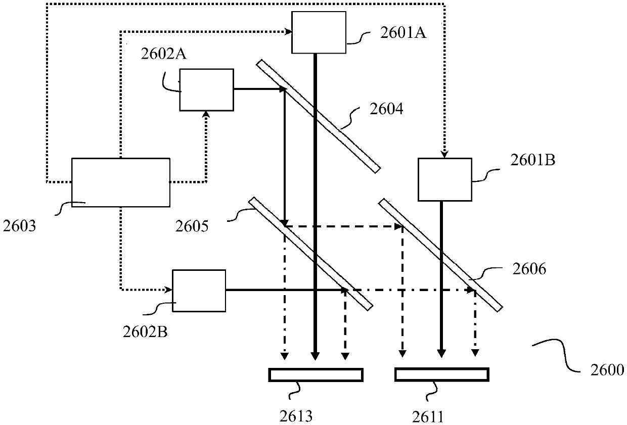
[0075] see Image 6 , Image 6 It is a schematic diagram of another embodiment of the light source system of the present invention. In this embodiment, the light source system 600 includes a light emitting device 1 , a light splitting system 2 , a first spatial light modulator 611 and a second spatial light modulator 613 . The light emitting device 1 includes an excitation light source 601 , a wavelength conversion layer 603 and a first driving device 605 .

[0076] This embodiment and Figure 5 Differences in the illustrated embodiments include:

[0077] The spectroscopic system 2 includes a first spectroscopic device 609, a second driving device 607 and a first control device (not shown). In order to improve the utilization rate of the light emitted by the light emitting device 1, the light source system 600 also includes a collecting lens 615 arranged on the optical path between the light emitting device 1 and the spectroscopic system 2, for collecting the yellow light ...


PUM


Abstract

An embodiment of the invention discloses a light source system comprising a lighting device, a light division system, a first spatial light modulator and a second spatial light modulator. The lighting device is used for emitting first light and second light in order. The light division system is used for dividing the first light from the lighting device into first-range wavelength light and second-range wavelength light which are emitted along a first light passage and a second light passage respectively; the light division system is further used for emitting at least part of the second light from the lighting device along the first light passage. The first spatial light modulator is used for modulating the light which is emitted by the light division system along the first passage. The second spatial light modulator is used for modulating at least part of the light which is emitted by the light division system along the second light passage. The light source system is high in lighting efficiency and low in cost.

Description

[0001] This application is a divisional application with the application number 201210370655.9 and the invention name "Light Source System and Related Projection System" submitted by the applicant on September 28, 2012. technical field [0002] The present invention relates to the field of illumination and display technology, in particular to a light source system and its related projection system. Background technique [0003] In the existing single-chip DMD (Digital Micromirror Device, digital micromirror device) system, multiple primary color lights alternately enter the DMD (DMD) and are modulated by it, and the modulated monochromatic light images are quickly alternately switched on the screen, and then The color image is formed by mixing the time-series monochromatic light images by using the residual visual effect of the human eye. However, in the prior art, R (red, red light), G (green, green light), and B (blue, blue light) three primary color lights are generally u...

Claims


Application Information

Patent Timeline
Patent Type & Authority Applications(China)
IPC IPC(8): G03B21/20G03B21/00G02B27/10F21V9/10F21V9/40
Inventor 胡飞李屹曹亮亮杨毅
Owner APPOTRONICS CORP LTD
Features
  • R&D
  • Intellectual Property
  • Life Sciences
  • Materials
  • Tech Scout
  • Unparalleled Data Quality
  • Higher Quality Content
  • 60% Fewer Hallucinations
Learn More