
Indoor visual positioning system and method

A visual positioning and positioning light technology, applied in the field of visual positioning, can solve the problems of limited positioning accuracy, complicated registration process, and poor flexibility, and achieve the effects of fast positioning tracking, convenient use, and fast positioning

Active Publication Date: 2014-12-17
徐州艾奇机器人科技有限公司
View PDF7 Cites 34 Cited by
  • Summary
  • Abstract
  • Description
  • Claims
  • Application Information

AI Technical Summary

Problems solved by technology

The first is stereo vision positioning, which can obtain more information, such as [Jirawinut R, Prakoonwit S, Cecelja F, etal visual odometer for pedestrian navigation. IEEE Transactions on Instrumentation and Measurement, 2004, 52(4): 1166 -1173] proposed a visual navigation system for indoor environments, but the algorithm is complex and the calculation cost is high
The second is full-dimensional visual positioning. This type of method can obtain a wide range of information, but the image distortion is relatively large, such as [Wang Jingshun, Chen Weidong, Cao Qixin. Research on robot self-positioning methods based on panoramic vision and odometer. Robotics, 2005, 27 (1): 41-45.] introduces a self-localization method applied to soccer robots
This invention uses two ordinary cameras to achieve high-precision measurement requirements, but its registration process is complicated and the degree of automation is not high
[0005] Single-use monocular vision positioning has insufficient environmental adaptability, and the positioning accuracy is limited by the accuracy of prior knowledge, while single-use binocular vision positioning method has complicated registration process, slow positioning speed and poor flexibility

Method used


Image

  • Indoor visual positioning system and method
  • Indoor visual positioning system and method
  • Indoor visual positioning system and method

Examples


Embodiment Construction

[0076] In order to further describe the technical features and effects of the present invention, the present invention will be further described below in conjunction with the accompanying drawings and specific embodiments.

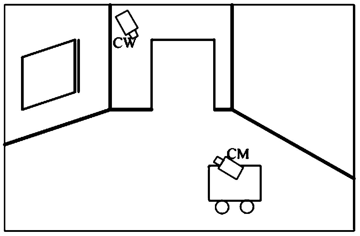
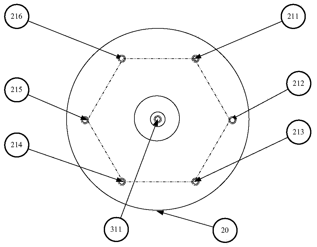
[0077] Reference Figure 1-11 As shown, an indoor visual positioning system uses two isomorphic cameras to jointly complete positioning and monitoring tasks. One of them is a fixed-position camera, called a fixed camera CW, which can be hung on the indoor wall to detect global environmental information And guide the movement of another camera; another camera is installed on the mobile carrier, called the mobile camera CM, used to detect the local information of the environment and cooperate to complete the binocular vision task. The hardware structure of the fixed camera CW and the mobile camera CM are the same, including a front panel 20, a power module 10, a sensor group 30, a communication module 40, and an information processing module 50. The front panel...


PUM


Abstract

The invention discloses an indoor visual positioning system and method. The indoor visual positioning system comprises a power module, a sensor group, an information processing module, a front faceplate and a wireless communication module, wherein the front faceplate is provided with a positioning lamp group. Two cameras of the indoor visual positioning system can be flexibly mounted on walls and mobile carriers and have a double-eye visual working mode and a single-eye visual working mode. The method based on the indoor visual positioning system comprises, firstly, utilizing the front faceplate information of the cameras to calibrate double-eye visual system external parameters; secondly, utilizing double-eye visual measurement accurate information to structure maps to provide prior knowledge form a subsequent single-eye positioning mode; finally, utilizing knowledge such as points, lines, planes and distances contained in the maps to start the single-eye visual positioning mode and to achieve efficient and rapid positioning. The indoor visual positioning system and method solves the problem that traditional visual positioning methods cannot give consideration to precision and speed simultaneously, improves the flexibility and the automation degree of a positioning system.

Description

Technical field [0001] The invention belongs to the technical field of visual positioning, and in particular relates to an indoor visual positioning system and method. Background technique [0002] Traditional positioning technologies usually include Global Positioning System (GPS) and dead reckoning methods. At present, the use of machine vision technology to realize the positioning of moving targets or the estimation of the attitude of moving carriers has become an effective supplement to the above-mentioned positioning technology, and has attracted wide attention from scholars at home and abroad. According to the different ways of using cameras, vision-based positioning methods are mainly divided into three categories. One is stereo vision positioning, this kind of method can obtain more information, as in the text [Jirawinut R, Prakoonwit S, Cecelja F, etal visual odometer for pedestrian navigation. IEEE Transactions on Instrumentation and Measurement, 2004, 52(4):1166 -117...

Claims


Application Information

Patent Timeline
IPC IPC(8): G06T7/00G06T7/20
Inventor 韩磊徐梦溪郑胜男黄陈蓉
Owner 徐州艾奇机器人科技有限公司
Learn More