Liquid ejecting head and liquid ejecting device
A liquid ejection head and nozzle technology, which is applied in printing and other directions, can solve the problems of short service life of nozzle plate, decrease of surface hydrophobicity, increase of printing cost, etc., so as to prolong service life, improve performance and reduce the possibility of delamination sexual effect
- Summary
- Abstract
- Description
- Claims
- Application Information
AI Technical Summary
Problems solved by technology
Method used
Image

Examples
Embodiment 1
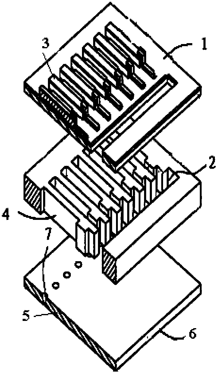
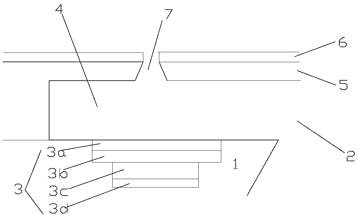
[0060] The inkjet head provided in this embodiment is a piezoelectric driven inkjet head, and its structure is as follows: figure 1 with 2 As shown, the nozzle plate 5 and the substrate 1 are included, and the nozzle 7 is formed on the nozzle plate 5, and the space between the nozzle plate 5 and the substrate 1 forms the above-mentioned pressure chamber 4, and the pressure chamber 4 passes through the nozzle plate 5. The nozzle 7 communicates with the outside world. In practical applications, the inkjet head may contain a plurality of nozzles 7 and a plurality of pressure chambers 4 , wherein the pressure chambers 4 communicate with the common chamber 2 , and the ink is distributed to each pressure chamber 4 from the common chamber 2 . The surface of the nozzle plate 5 facing away from the pressure chamber 4 is provided with a superhydrophobic material layer 6, which can form a superhydrophobic material layer 6 in the area around the nozzle 7 after the nozzle 7 is formed; it ...
Embodiment 2
[0067] The inkjet head provided in this embodiment is a thermal bubble inkjet head, and its structure is as follows: Figure 4 As shown, the difference from Embodiment 1 is that the piezoelectric element 3 arranged outside the pressure chamber 4 is replaced by a thin-film resistance layer 3' arranged in the pressure chamber 4, and the material of the thin-film resistance layer 3' can be, for example, Tantalum Aluminum Alloy, Nickel Chrome Alloy, Tungsten Silicon Nitride or Titanium Nitride. When the control signal is applied, the thin-film resistance layer 3' heats the ink to about 340°C at a rate of 1000°C / μs, and the volatile components in the ink are vaporized to generate bubbles, which are like a piston, which are continuously generated toward the nozzle plate 5 The thrust in the direction pushes the ink drop out from the nozzle 7.
[0068] Wherein, the superhydrophobic material layer 6 is a butyl methacrylate-ethylene glycol dimethacrylate copolymer layer prepared by an ...
Embodiment 3
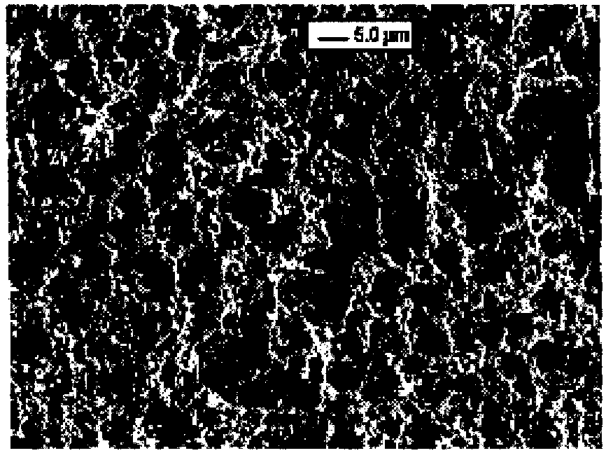
[0071] The structure and manufacturing method of the inkjet head provided in this example are the same as those in Example 2, except that the superhydrophobic material layer 6 is a styrene-divinylbenzene copolymer layer prepared by in-situ polymerization. The preparation method is as follows: using 24 parts by weight of ethylene, 16 parts by weight of 1,4-divinylbenzene, 50 parts by weight of 1-n-decyl alcohol and 10 parts by weight of tetrahydrofuran as monomers, 2,2'-azobisiso 1 weight part of butyronitrile was used as a thermal initiator, reacted at 70°C for 24 hours, and carried out in-situ polymerization to prepare a styrene-divinylbenzene copolymer layer, which was then washed with formaldehyde and dried in the air, so that the nozzle plate A superhydrophobic material layer is formed on the surface, which has a porous surface microstructure, such as Figures 6b-6c As shown, wherein 10 μm and 400nm are contrasting lengths, the porous surface pore diameter of the superhydr...
PUM
 Abstract
Description
Claims
Application Information
 - R&D
- Intellectual Property
- Life Sciences
- Materials
- Tech Scout
- Unparalleled Data Quality
- Higher Quality Content
- 60% Fewer Hallucinations
Browse by: Latest US Patents, China's latest patents, Technical Efficacy Thesaurus, Application Domain, Technology Topic, Popular Technical Reports.
© 2025 PatSnap. All rights reserved.Legal|Privacy policy|Modern Slavery Act Transparency Statement|Sitemap|About US| Contact US: help@patsnap.com