Heating chamber and plasma processing apparatus

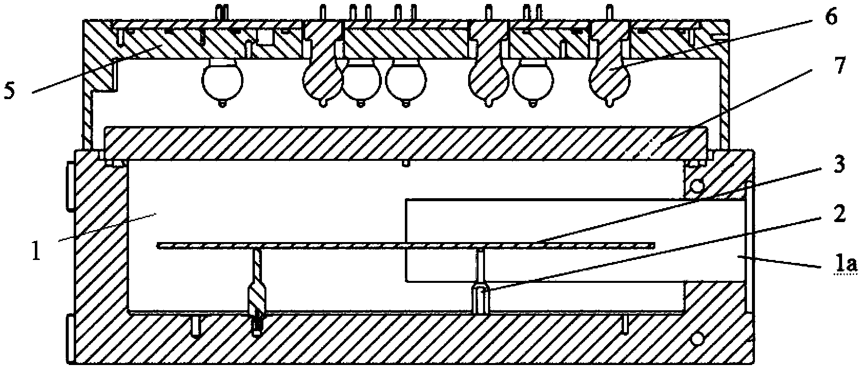
A technology for heating chambers and chambers, applied in ion implantation plating, metal material coating technology, semiconductor/solid-state device manufacturing, etc., which can solve differences, destroy the symmetry of the circular inner peripheral wall, and uneven temperature of the substrate 3, etc. problem, to achieve the effect of improving the uniformity of the process, improving the uniformity of temperature, and avoiding adverse effects

Inactive Publication Date: 2014-12-24
BEIJING NAURA MICROELECTRONICS EQUIP CO LTD
View PDF3 Cites 9 Cited by
  • Summary
  • Abstract
  • Description
  • Claims
  • Application Information

AI Technical Summary

Problems solved by technology

[0004] The above-mentioned PVD equipment inevitably has the following problems in practical applications, that is, since the film transfer port 1a is provided on the inner peripheral wall of the degassing chamber 1, this destroys the symmetry of the circular inner peripheral wall of the degassing chamber 1, As a result, the inner peripheral wall cannot evenly reflect the heat radiated by the heating bulb 6, resulting in uneven temperature distribution in the degassing chamber 1, and because most of the heat radiated by the heating bulb 6 to the sheet transfer port 1a is difficult to reflect On the substrate 3, this will cause the difference in the heat obtained by the region of the substrate 3 corresponding to the transfer opening 1a and the region corresponding to other positions of the inner peripheral wall, thereby causing the temperature of the substrate 3 to be uneven, thereby reducing the uniformity of the process

Method used


Image

  • Heating chamber and plasma processing apparatus
  • Heating chamber and plasma processing apparatus
  • Heating chamber and plasma processing apparatus

Examples


Embodiment Construction

[0024] In order for those skilled in the art to better understand the technical solution of the present invention, the heating chamber and the plasma processing equipment provided by the present invention will be described in detail below with reference to the accompanying drawings.

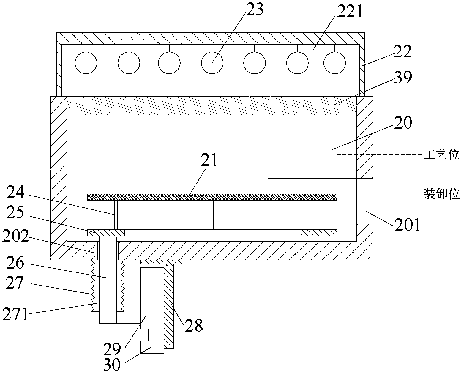
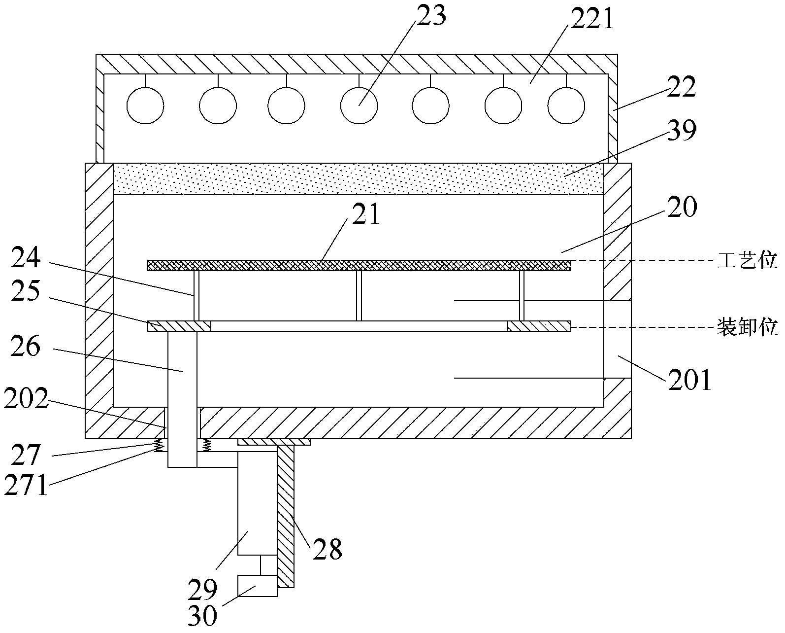
[0025] Figure 2A The sectional view of the heating chamber provided by the present invention when the processed workpiece is in the loading and unloading position. Figure 2B The cross-sectional view of the heating chamber provided by the present invention when the processed workpiece is in the process position. image 3 A top view of the ring support of the heating chamber provided by the present invention. Please also refer to Figure 2A , 2B and image 3 , in this embodiment, a heating unit is arranged on the top of the heating chamber 20, the heating unit includes an upper body cover 22 arranged on the top of the heating chamber 20, and a heating lamp 23 located in the upper body cover 2...


PUM

PropertyMeasurementUnit
heightaaaaaaaaaa

Abstract

The invention provides a heating chamber and a plasma processing apparatus. The top of the heating chamber is provided with a heating unit for irradiating heat energy to the interior of the heating chamber in a heat radiation manner; the inner circumference wall of the heating chamber is provided with a piece-transferring opening for moving a to-be-processed workpiece in and out of the heating chamber; and the heating chamber comprises a bearing device. The bearing device comprises a lifting unit and ejection pin devices; the ejection pin devices are disposed in the heating chamber and are used for supporting the to-be-processed workpiece; the lifting unit is used for driving the ejection pin devices to rise or descend, so as to drive the to-be-processed workpiece on the ejection pin devices to rise to a preset process position above the piece-transferring opening to carry out the process or descend to a preset loading and unloading position corresponding to the piece-transferring opening to carry out loading and unloading operations. The heating chamber provided by the invention can heat the to-be-processed workpiece uniformly, and thus temperature uniformity of the to-be-processed workpiece is increased and uniformity of the process can be increased.

Description

technical field [0001] The invention relates to the technical field of microelectronic processing, in particular to a heating chamber and plasma processing equipment. Background technique [0002] Physical vapor deposition (Physical Vapor Deposition, hereinafter referred to as PVD) technology is a commonly used processing technology in the field of microelectronics, for example, it is used to process copper interconnect layers in integrated circuits. The production of copper interconnection layer mainly includes the steps of degassing, pre-cleaning, Ta(N) deposition, and Cu deposition. The degassing step is to remove water vapor and other volatile impurities on the substrate and other processed workpieces. When performing the degassing step, it is not only necessary to heat the substrate rapidly to about 350°C, but also to ensure that the substrate is heated evenly, otherwise the volatile impurities generated in some areas of the substrate will not be removed cleanly, which ...

Claims


Application Information

Patent Timeline
Patent Type & Authority Applications(China)
IPC IPC(8): C23C14/22
CPCH01L21/68742H01L21/67115
Inventor 武学伟
Owner BEIJING NAURA MICROELECTRONICS EQUIP CO LTD
Why Eureka
Try Eureka