Automatic rural network low-voltage in situ reactive compensation adjustment method

An automatic adjustment, low-voltage technology, applied in reactive power compensation, reactive power adjustment/elimination/compensation, etc., can solve the problem of insufficient capacity of main distribution transformer, long power supply radius of distribution station area, and surge of load in distribution station area To achieve the effects of reducing the three-phase unbalance rate, improving the management level of power distribution in rural power grids, and improving output efficiency and power factor

Inactive Publication Date: 2014-12-24
STATE GRID CORP OF CHINA +2
View PDF2 Cites 5 Cited by
  • Summary
  • Abstract
  • Description
  • Claims
  • Application Information

AI Technical Summary

Problems solved by technology

With the rapid development of society, the living standards of farmers continue to improve, and the demand for electricity in rural areas is also increasing rapidly. A large number of single-phase equipment has been put into use, which has caused a surge in the load of the distribution station area, and the capacity of the main distribution transformer is insufficient; The power supply radius in the area is too long, the wire diameter is too thin, and the active power loss is too large; the reactive power of the line is seriously under-compensated, resulting in a large terminal voltage loss; the three-phase load is seriously unbalanced, resulting in serious voltage loss
[0003] With the extensive use of single-phase loads in rural areas, the three-phase imbalance of distribution transformer loads will only become more serious, and it will develop dynamically over time. Manual adjustment alone is feasible in the short term, but it is difficult to achieve the ideal goal.

Method used


Image

  • Automatic rural network low-voltage in situ reactive compensation adjustment method

Examples


Embodiment Construction

[0027] Below in conjunction with accompanying drawing, the present invention will be further explained and illustrated:

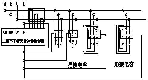
[0028] see figure 1 , a method for automatically adjusting reactive power compensation in-situ for low-voltage rural power grids, the specific steps of which are as follows:

[0029] ① Change the transformer from small to large to increase capacity;

[0030] ②Install transformers, low-voltage sub-networks, voltage regulating networks, and phase-changing transformers to shorten the power supply radius;

[0031] ③ According to the capacity of the distribution transformer, increase the automatic switching reactive power compensation device on the low-voltage side of the distribution transformer and the reactive power compensation device of the low-voltage line to improve the power factor and voltage;

[0032] ④ Install in-situ compensation devices for high-power users;

[0033] ⑤Detect and adjust the three loads in time to ensure that the three-phase unbala...


PUM


Abstract

The invention discloses an automatic rural network low-voltage in situ reactive compensation adjustment method. Capacity increasing is conducted on a transformer, the transformer is additionally arranged, low-voltage network distribution is conducted, a voltage regulating network is installed, a variable-phase transformer is installed, a distribution transform low-voltage-side automatic switching reactive compensation device and a low-voltage line reactive compensation device are additionally arranged, a in-situ compensator device is installed for a large-power user, and a voltage boosting device is additionally arranged at the branch line tail end. The voltage boosting device comprises a three-phase unbalanced adjustment reactive compensation controller, a star connection capacitor and an angle connection capacitor. The output efficiency of the transformer is improved and the power factor of the transformer is increased through connecting the star connection capacitor and the angle connection capacitor into phases and being in combination with the three-phase unbalanced adjustment reactive compensation controller. The method starts from solving three-phase unbalance and reactive compensation, the branch line voltage change is tracked automatically, the reactive power compensation and the active power are controlled to transfer automatically among the phases to achieve balance, the transformer output efficiency is improved, the transformer power factor is increased, reasonable adjustment of the branch line voltage is achieved, the line loss is reduced, and the branch line voltage is effectively boosted.

Description

Technical field: [0001] The invention relates to a method for rectifying low voltage in a rural station area, in particular to an automatic adjustment method for in-situ reactive power compensation of low voltage in a rural power grid, and belongs to the technical field of rural power grid transformation. Background technique: [0002] Voltage is an important index to measure the quality of power supply. The quality of voltage is a matter of people's livelihood that is related to the people's "good use of electricity" and "easy use of electricity". With the rapid development of society, the living standards of farmers continue to improve, and the demand for electricity in rural areas is also increasing rapidly. A large number of single-phase equipment has been put into use, which has caused a surge in the load of the distribution station area, and the capacity of the main distribution transformer is insufficient; The power supply radius in the area is too long, the wire diam...

Claims


Application Information

Patent Timeline
Patent Type & Authority Applications(China)
IPC IPC(8): H02J3/18
CPCY02E40/30
Inventor 熊卿府郑阳辛军闫庆芳陈志刚杨琳
Owner STATE GRID CORP OF CHINA
Why Eureka
Try Eureka