
Valley-switching digital control circuit of switch power source

A technology of digital control circuit and switching power supply, which is applied in the direction of control/regulation system, electrical components, and regulation of electric variables, etc. It can solve the problems of limited design of switching power supply drive circuit, inaccurate conduction position at the bottom of the valley, abnormal resonance and non-operation, etc. , achieve the effect of improving EMI characteristics, good compatibility and reducing switching loss

Active Publication Date: 2014-12-24
WUXI CHIPOWN MICROELECTRONICS
View PDF5 Cites 5 Cited by
  • Summary
  • Abstract
  • Description
  • Claims
  • Application Information

AI Technical Summary

Problems solved by technology

[0006] The technical problem to be solved by the present invention is to address the above-mentioned deficiencies in the background technology and provide a valley conduction drive circuit for switching power supplies, which can solve the valley bottom caused by the large switching loss of the driving switch tube, the constant operating frequency when stable, and the vibration of the resonance period in the resonance area. Inaccurate conduction position, non-operation when resonance is abnormal, and limited design of switching power supply drive circuit

Method used


Image

  • Valley-switching digital control circuit of switch power source
  • Valley-switching digital control circuit of switch power source
  • Valley-switching digital control circuit of switch power source

Examples


Embodiment Construction

[0043] The technical solution of the invention will be described in detail below in conjunction with the accompanying drawings.

[0044]The invention describes in detail a valley conduction digital control structure for a switching power supply. Using the power supply system of the present invention, while effectively reducing switching losses, accurate conduction at the bottom of the valley is achieved, and the conduction mode is switched from the valley bottom conduction mode to real-time conduction when the resonance cycle is abnormal, and is suitable for discontinuous mode switching power supply chips in PWM and PFM modes , EMI characteristics are good.

[0045] The control circuit of the present invention is as Figure 4 It mainly includes: valley conduction digital control structure, including resonant period comparator, reference voltage 0.1V, first resonant period valley digital operation module, second to n resonant period valley bottom digital operation module, abno...


PUM


Abstract

The invention discloses a valley-switching digital control circuit of a switch power source, and belongs to the technical field of switch power source circuit design. The valley-switching digital control circuit comprises a voltage feedback detection module, a current feedback detection module, an arithmetic unit, a valley-switching digital control module, a and gate device and a PWM generating module, wherein the voltage feedback detection module is used for collecting switch power source voltage feedback signals, the current feedback detection module is used for collecting drive switch tube currents, the arithmetic unit is used for obtaining drive switch tube breakover signals according to voltage feedback detection module output signals and current feedback detection module output signals, the valley-switching digital control module is used for obtaining valley-switching signals according to the voltage feedback detection module output signals, the and gate device is used for conducting and operation on the drive switch tube breakover signals and the valley-switching signals, and the PWM generating module is used for generating actual duty ratio signals according to the operation result of the and gate device. By means of the valley-switching digital control circuit, the switch loss is effectively reduced while accurate valley switching is achieved, the valley-switching mode is switched into the real-time breakover mode when the resonant period is abnormal, and the valley-switching digital control circuit is suitable for discontinuous-mode switch power source chips in the PWM mode and PFM mode.

Description

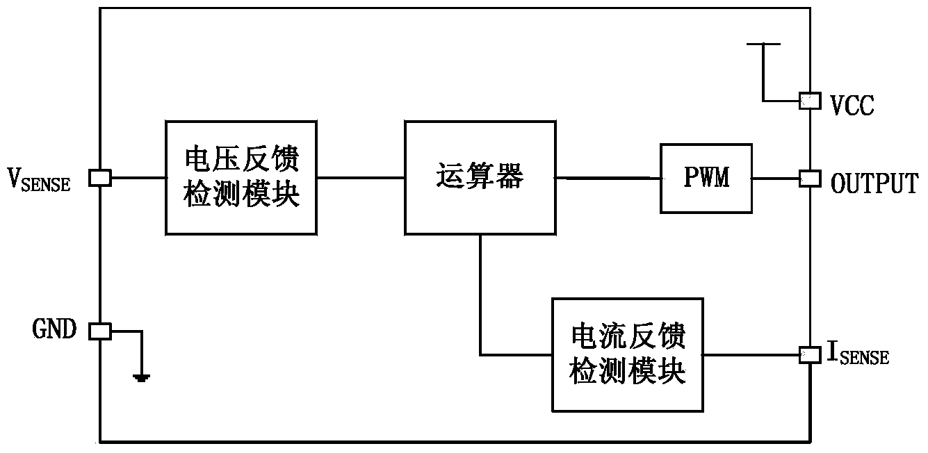
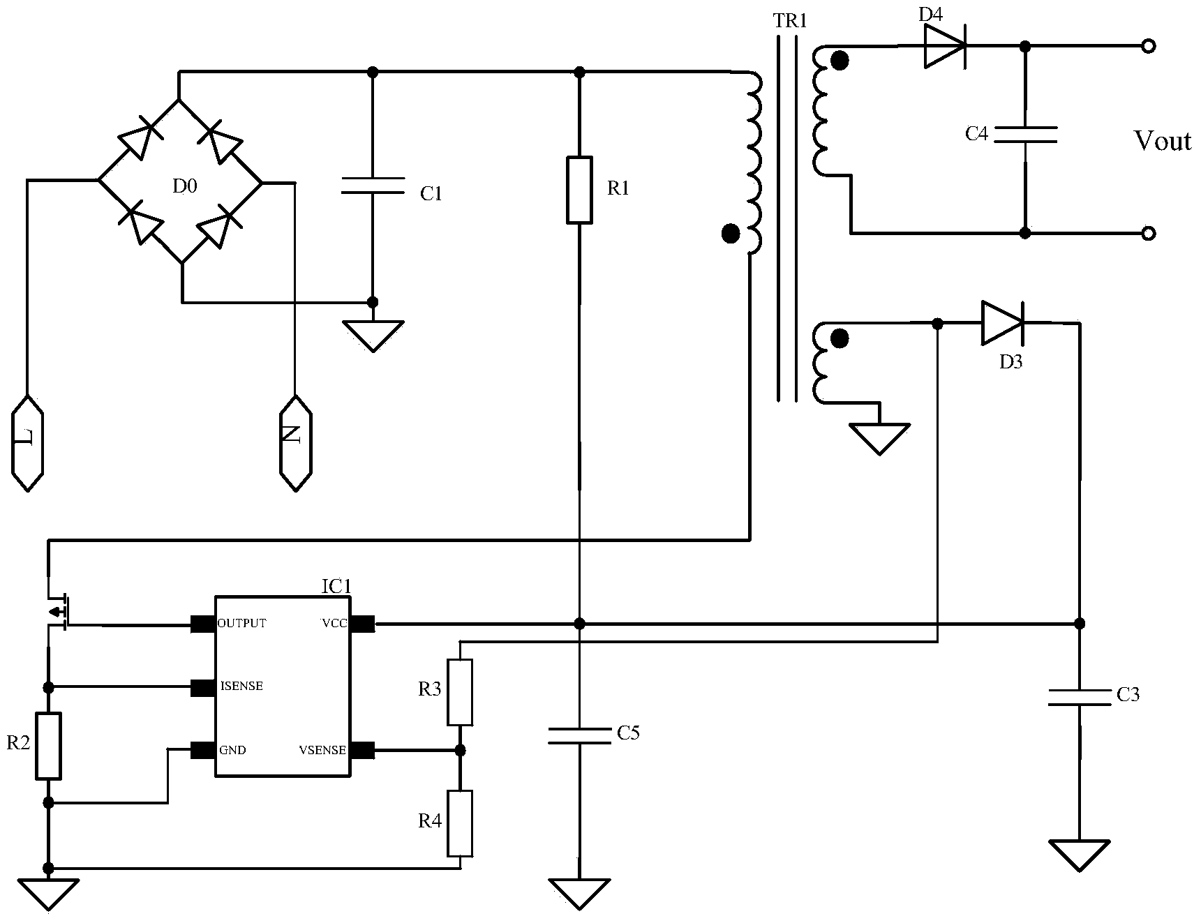
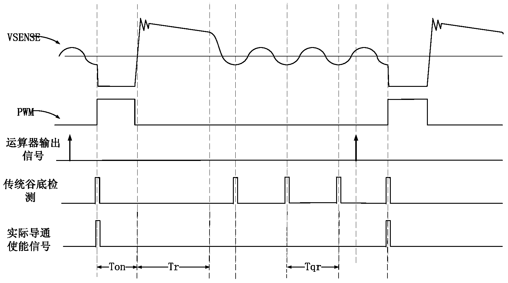
technical field [0001] The invention discloses a valley conduction digital control circuit of a switching power supply, which belongs to the technical field of switching power supply circuit design. Background technique [0002] With the popularity of portable electronic devices, switching power supplies have become the main power supply solutions for such electronic devices. figure 1 A traditional switching power supply chip structure is given. The chip mainly includes: voltage feedback detection module, current feedback detection module, arithmetic unit, PWM generation module. figure 2 A system scheme of a traditional switching power supply chip structure is given. The system mainly includes: rectifier bridge D0, filter capacitor C1, transformer TR1, power chip IC1, switch tube connected to the OUTPUT pin of the power chip IC1, and switch tube connected The CS sampling circuit, the DC output stage connected to the secondary side of the transformer (composed of diode D4 a...

Claims


Application Information

Patent Timeline
Patent Type & Authority Applications(China)
IPC IPC(8): H02M3/28H02M3/335
Inventor 李海松陶平易扬波
Owner WUXI CHIPOWN MICROELECTRONICS
Learn More