Driving circuit used for all-digital alternating-current servo driver
A technology of AC servo and drive circuit, applied in the direction of AC motor control, electrical components, output power conversion devices, etc., can solve problems such as energy discharge control, voltage overvoltage, lack of drive for IGBT modules, etc., to achieve high reliability, Full-featured and easy-to-use effects
- Summary
- Abstract
- Description
- Claims
- Application Information
AI Technical Summary
Problems solved by technology
Method used
Image
Examples
Embodiment Construction
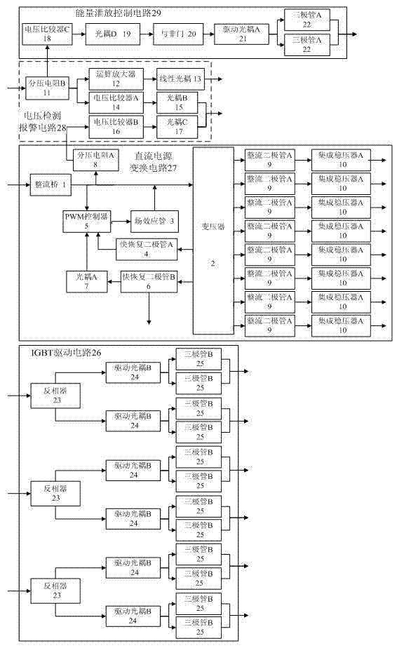
[0019] A driving circuit for an all-digital AC servo driver, comprising: an IGBT driving circuit 26 . It also includes: a DC power conversion circuit 27 , a voltage detection and alarm circuit 28 and an energy discharge control circuit 29 .
[0020] The DC power conversion circuit 27 includes: a rectifier bridge 1, a transformer 2, a field effect transistor 3, a fast recovery diode A4, a PWM controller 5, a fast recovery diode B6, an optocoupler A7, a voltage dividing resistor A8, a rectifier diode 9 and Integrated voltage regulator 10. The voltage detection and alarm circuit 28 includes: a voltage dividing resistor B11, an operational amplifier 12, a linear optocoupler 13, a voltage comparator A14, an optocoupler B15, a voltage comparator B16 and an optocoupler C17. The energy discharge control circuit 29 includes: a voltage comparator C18, an optocoupler D19, a NAND gate 20, a drive optocoupler A21 and a triode A22. The IGBT driving circuit 26 includes: an inverter 23, a d...
PUM
 Abstract
Description
Claims
Application Information
 - R&D
- Intellectual Property
- Life Sciences
- Materials
- Tech Scout
- Unparalleled Data Quality
- Higher Quality Content
- 60% Fewer Hallucinations
Browse by: Latest US Patents, China's latest patents, Technical Efficacy Thesaurus, Application Domain, Technology Topic, Popular Technical Reports.
© 2025 PatSnap. All rights reserved.Legal|Privacy policy|Modern Slavery Act Transparency Statement|Sitemap|About US| Contact US: help@patsnap.com

