Intrusive replacement valve and controllable conveying device thereof

A technology for delivery devices and valves, applied in the field of interventional therapy devices and medical devices, to achieve the effects of reducing release resistance, reliable fixation, and avoiding tearing

Active Publication Date: 2015-01-07
BEIJING MED ZENITH MEDICAL SCI CORP LTD
View PDF12 Cites 7 Cited by
  • Summary
  • Abstract
  • Description
  • Claims
  • Application Information

AI Technical Summary

Problems solved by technology

In China, more than 85% of TOF patients adopt RVOT expansion with transvalvular patch, and the inner diameter of the pulmonary valve ring is much larger than 22mm. Therefore, the above two foreign valves are basically not suitable for Chinese patients.

Method used


Image

  • Intrusive replacement valve and controllable conveying device thereof
  • Intrusive replacement valve and controllable conveying device thereof
  • Intrusive replacement valve and controllable conveying device thereof

Examples


Embodiment 1

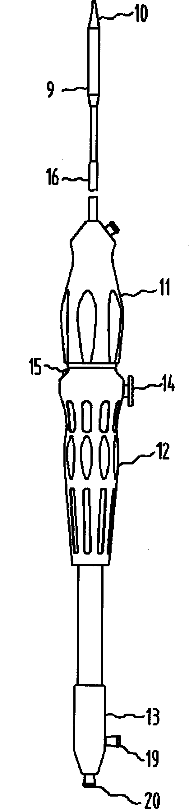
[0059] see Figure 5a It is a schematic diagram of the surgical procedure of interventional valve replacement, Figure 6 It is a schematic diagram of the release process of the interventional replacement valve. For routine femoral vein puncture, under the guidance of DSA (Digital subtraction angiography, digital subtraction angiography), the first choice is to penetrate the guide wire from the femoral vein to the right ventricle25 and then enter the branch of the pulmonary artery29. The delivery device enters the main pulmonary artery 27 along the guide wire. After positioning, the outer tube 9 of the delivery device is slowly withdrawn. After the interventional replacement valve is opened, the stenotic or damaged pulmonary valve 28 is opened and fixed, and then the safety button 15 is operated to place the middle handle 12 on the The switch button 14 is unlocked, press the switch button 14 to switch the delivery device to the push operation mode to store the conical head end...

Embodiment 2

[0061] see Figure 5b It is a schematic diagram of the surgical procedure of interventional valve replacement. For routine subclavian vein puncture, under the guidance of DSA (Digital subtraction angiography, digital subtraction angiography), the first choice is to penetrate the guide wire from the subclavian vein to the right ventricle 25 and then into the main pulmonary artery 27, and then follow the procedure in Example 1. The method is used to place an interventional replacement valve and complete the operation.

Embodiment 3

[0063] see Figure 5c It is a schematic diagram of the surgical procedure of interventional valve replacement. Conventional thoracotomy apical puncture, under the guidance of DSA (Digital subtraction angiography, digital subtraction angiography), the first choice is to penetrate the guide wire from the apex of the heart to the right ventricle 25 and then enter the main pulmonary artery 27, and then follow the method in Example 1 Place the interventional replacement valve and complete the operation.


PUM

PropertyMeasurementUnit
Tensile strengthaaaaaaaaaa

Abstract

The invention discloses an intrusive replacement valve which comprises a support, a sealing membrane and a valve leaf. The support is of a grid structure and in the shape of a waist drum, two ends of the support are large while the middle of the same is small, and three connecting lugs are arranged at one end of the support. The support is highly matched with a right ventricular outflow tract and a main pulmonary artery blood vessel respectively, thereby being less prone to displacement after release, and the sealing membrane is sewn around the inner side of the support , and the valve leaf is sewn on a grid in the middle of the support. The invention further provides a controllable conveying device. A connecting claw connected with the valve and an outer pipe containing the same are arranged at the front end of the controllable conveying device, and the connecting claw and the outer pipe mount the valve in the conveying device and realize a function of recovering part of the valve in the process of releasing through a control handle of the controllable conveying device. The control handle can realize rotating release and pushing release of the valve and can switch between rotating release and pushing release, so that operating difficulty is lowered, and operating success rate is increased.

Description

technical field [0001] The present invention relates to the field of medical devices, in particular to the field of interventional therapy devices; more specifically, to heart valve technology, in particular to an interventional replacement valve and a controllable delivery device thereof. Background technique [0002] In China, patients with right ventricular outflow tract (RVOT) and pulmonary artery stenosis such as tetralogy of Fallot (TOF) generally undergo RVOT transvalvular patch surgery (RVOT, pulmonary artery longitudinal incision and patch to expand Lumen diameter) to relieve RVOT and pulmonary artery stenosis will cause pulmonary valve annulus to expand and valve leaflets to coapt poorly (some patients even resect the diseased pulmonary valve during surgery), resulting in significant regurgitation (PR). Many foreign centers will implant artificial blood vessels with valves in the RVOT. Although there will be no PR in the short term, after long-term application, the...

Claims


Application Information

Patent Timeline
Patent Type & Authority Applications(China)
IPC IPC(8): A61F2/24A61L27/38A61L27/06
Inventor 周庆亮代高旭史欢欢可大年孟坚
Owner BEIJING MED ZENITH MEDICAL SCI CORP LTD
Why Eureka
Try Eureka