Middle-low-temperature flue gas desulfurization, dedusting and denitration and denitration catalyst thermal-desorption integrated device

A denitrification catalyst, desulfurization and dust removal technology, applied in the direction of catalyst regeneration/reactivation, physical/chemical process catalyst, combined device, etc., can solve the problems that it is impossible to install bag filter and denitration reactor at the same time, affecting the efficiency of medium and low temperature denitrification, etc. Achieve the effects of improving catalytic efficiency and service life, reducing operating costs, and improving denitrification efficiency

Active Publication Date: 2015-01-07
ACRE COKING & REFRACTORY ENG CONSULTING CORP DALIAN MCC
5 Cites 37 Cited by

AI-Extracted Technical Summary

Problems solved by technology

However, some engineering projects are limited by the site, and it is impossible to install bag filter and denitrification reactor at the same time
In addition, the low-temperature denitrification catalyst will oxidize a small part of sulfur dioxide into sulfur trioxide,...

Method used

[0029] The upper part of the desulfurization and dust collection and purification section 1 is composed of a flue gas inlet 1c, a uniform air flow deflector 1d, a filter bag 1e, and a pulse injection device 1f. The flue gas inlet 1c is set on the side tower above the desulfurization dust collection and purification section 11a, and multiple rows of filter bags 1e are vertically embedded in the flower plate holes of the desulfurization dust collection and purification section 1, and are evenly distributed along the longitudinal direction, and the air flow is evenly distributed and guided The plate 1d is arranged between the flue gas inlet 1c an...

Abstract

The invention relates to a middle-low-temperature flue gas desulfurization, dedusting and denitration and denitration catalyst thermal-desorption integrated device. The integrated device comprises a desulfurization, dust-collection and purification section, an desorption, ammonia-spraying and mixing section and a denitration reaction section which are integrated in a tower body from bottom to top, wherein the desulfurization, dust-collection and purification section comprises an ash bin, a closed dust discharging valve, a flue gas inlet, an airflow uniform-distribution and flow-guiding plate, filter bags and a pulse-jet device; the desorption, ammonia-spraying and mixing section comprises an ammonia-spraying structural body, a thermal desorption gas conveying-jetting structural body and mixed flow-equalizing structural bodies; the denitration reaction section comprises a denitration catalyst and a purified flue gas outlet. Compared with the prior art, the integrated device has the beneficial effects that (1) the processes of desulfurization, dedusting and denitration of flue gas as well as the thermal desorption of the denitration catalyst are integrated; (2) the service life of the denitration catalyst is long; (3) the denitration efficiency is high; (4) ammonia gas and flue gas as well as high-temperature thermal desorption gas and flue gas are in full contact with each other; (5) the denitration catalyst can be regenerated through online thermal desorption; (6) a denitration catalyst dust-cleaning system can be omitted.

Application Domain

Technology Topic

Image

  • Middle-low-temperature flue gas desulfurization, dedusting and denitration and denitration catalyst thermal-desorption integrated device
  • Middle-low-temperature flue gas desulfurization, dedusting and denitration and denitration catalyst thermal-desorption integrated device

Examples

  • Experimental program(1)

Example Embodiment

[0023] The specific embodiment of the present invention will be further described below in conjunction with accompanying drawing:
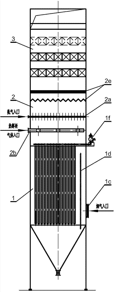
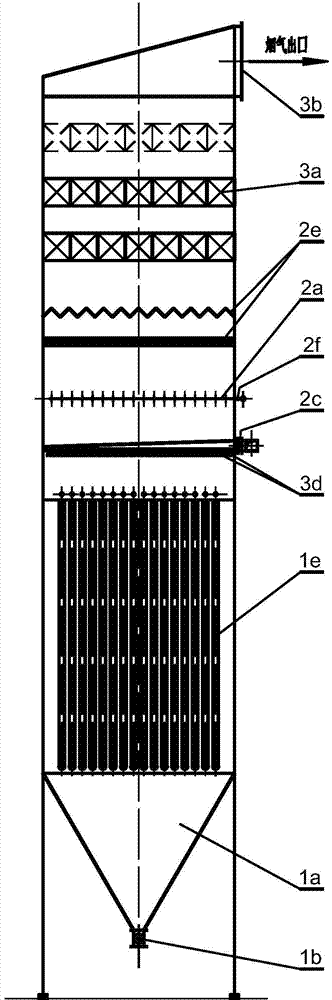
[0024] See Figure 1-Figure 2 , is a structural schematic diagram of the present invention, the medium and low temperature flue gas desulfurization, dust removal, denitrification and denitrification catalyst thermal analysis integrated device of the present invention, including a desulfurization, dust collection and purification section 1, an analysis and ammonia injection mixing section 2 and a bottom-up integrated in a tower body The denitrification reaction section 3, the desulfurization dust collection and purification section 1 is composed of an ash bin 1a, an airtight ash discharge valve 1b, a flue gas inlet 1c, a uniform air flow deflector 1d, a filter bag 1e and a pulse injection device 1f; The ammonia mixing section 2 is composed of an ammonia injection structure 2a, a thermal analysis gas delivery injection structure 2b, and a mixing and uniform flow structure 2e; the denitration reaction section 3 is composed of a denitration catalyst 3a and a purified flue gas outlet 3b.
[0025] The ash bin 1a is located at the bottom of the tower body, and the airtight ash discharge valve 1b is installed at the outlet of the ash bin 1b; the flue gas inlet 1c is set on the middle tower body of the desulfurization dust collection and purification section 1, and multiple rows of filter bags 1e is vertically embedded in the hole of the flower plate, and is evenly distributed along the longitudinal direction. The air flow uniform distribution deflector 1d is set between the flue gas inlet 1c and the filter bag 1e, and the upper part of the filter bag 1e is equipped with a pulse injection device 1f.
[0026] The pyrolysis gas transport injection structure 2b is composed of a plurality of air supply ducts arranged in parallel, each air supply duct is provided with an air volume regulating valve 2c, and the air supply ducts in the tower are evenly distributed with orifice air supply outlets 2d; The ammonia injection structure is set above the thermal analysis gas delivery injection structure 2b, and consists of multiple ammonia injection pipelines arranged in parallel, each ammonia injection pipeline is equipped with an ammonia injection regulating valve 2f, and the ammonia injection pipeline is evenly distributed 口; the mixed flow equalizing structure 2e is located above the ammonia spraying structure 2a, and consists of 1 to 4 layers of porous plates in the shape of arc corrugations or angular corrugations, and the two adjacent layers are separated by an angle of 90° according to the corrugation direction Staggered arrangement.
[0027] The denitration catalysts 3a are arranged in 2-4 layers, and the outlet 3b for purifying flue gas is arranged at the top of the tower.
[0028] The bottom of the desulfurization dust collection and purification section 1 is composed of an ash bin 1a and an airtight ash discharge valve 1b, and the airtight ash discharge valve 1b is located at the outlet of the ash bin 1a. The ash bin 1a is used to collect and store the particles separated from the flue gas. One function of the airtight ash discharge valve 1b is to prevent the outside air from penetrating into the device through the discharge port to reduce the temperature of the flue gas. The other function is to discharge the ash bin 1a to collect of dust particles.
[0029] The upper part of the desulfurization and dust collection and purification section 1 is composed of the flue gas inlet 1c, the airflow uniform distribution deflector 1d, the filter bag 1e, and the pulse injection device 1f. The flue gas inlet 1c is set on the side tower above the desulfurization dust collection and purification section 11a, and multiple rows of filter bags 1e are vertically embedded in the flower plate holes of the desulfurization dust collection and purification section 1, and are evenly distributed along the longitudinal direction, and the air flow is evenly distributed and guided The plate 1d is arranged between the flue gas inlet 1c and the filter bag 1e. Uniform distribution of air flow The deflector 1d is a labyrinth structure composed of angled steel plates, which can roughly separate the coarse coal powder contained in the dust gas, and at the same time guide the dust-laden flue gas, so that the air flow on the surface of the filter bag 1e is evenly distributed , to avoid dusty gas directly washing the surface of the filter bag 1e, affecting the efficiency and service life of the filter bag 1e. The pulse blowing device 1f is set in the air purification area on the upper part of the filter bag 1e, and is used for pulse back blowing and dust removal of the filter bag 1e.
[0030] The upper part of the desulfurization dust collection and purification section 1 is the analytical ammonia injection mixing section 2, which is composed of an ammonia injection structure 2a, a thermal analysis gas delivery injection structure 2b and a mixing and equalizing structure 2e. The pyrolytic gas delivery injection structure 2b is arranged on the upper part of the pulse injection device 1f, and is composed of a plurality of air supply pipes arranged in parallel, and each air supply pipe is equipped with an air volume regulating valve 2c to transport the high-temperature heat inside the equipment. The analytical gas is evenly transported to the cross section of the device through the orifice air supply ports 2d evenly distributed on the air supply duct. The ammonia injection structure 2a is arranged on the upper part of the pyrolysis gas delivery injection structure 2b, and is composed of a plurality of ammonia injection pipelines arranged in parallel. Ammonia injection regulating valves 2f are provided on the ammonia pipelines. Analyzing the top of the ammonia injection mixing section 2, there is a mixing and evening structure 2e. The mixing and evening structure 2e is made of an orifice plate, which is in the shape of arc corrugated or angular corrugated. The mixing and evening structure 2e can have 1 to 4 layers , and two adjacent layers are staggered at a 90° angle in the direction of the corrugation.
[0031] The denitrification reaction section 3 is located at the top of the integrated device for desulfurization, dust removal, denitrification and denitration catalyst thermal analysis of the present invention, and consists of a denitration catalyst 3a and a purified flue gas outlet 3b. The denitration catalyst 3a is composed of 2-4 structural layers. The purified flue gas outlet 3b is arranged on the top of the device, with the opening facing one side.
[0032]The working principle of the low-temperature flue gas desulfurization, dust removal, denitrification and denitrification catalyst thermal analysis integrated device of the present invention is: when the equipment is running, the dust-laden flue gas enters the desulfurization, dust collection and purification section 1 from the flue gas inlet 1c, and is evenly distributed with the airflow deflector 1d contact, the large particles of dust directly fall into the bottom of the ash bin 1a under the action of inertia, and the air flow passes through the deflector 1d of the uniform air distribution deflector, and is evenly distributed on the outer surface of the filter bag 1e. The incompletely reacted desulfurization agent and desulfurization ash in the flue gas are filtered through the filter bag 1e and captured on the outer surface of the filter bag 1e. When the flue gas passes through the dust layer, the sulfur dioxide in the flue gas and the unreacted desulfurization agent Particles fully contact and react, which can increase the desulfurization efficiency by more than 30%. By using the pulse injection device 1f to regularly inject compressed air, the particles captured by the filter bag 1e are blown down to the bottom of the ash bin 1a, and the dust filtered and purified The gas then enters the analytical ammonia injection mixing section 2. The ammonia gas is evenly sent into the tower through the ammonia injection pipe of the ammonia injection structure 2a, and fully mixed and contacted with the flue gas. Under the action of pressure equalization and mixing of the mixed flow equalization structure 2e, the flue gas and ammonia gas are uniformly mixed, and at the same time, the flue gas entering the denitration reaction section 3 is uniformly distributed in the velocity field and temperature field in the cross section of the device. When the flue gas fully mixed with ammonia passes through the denitration catalyst 3a, under the catalysis of the catalyst, the ammonia reduces nitrogen oxides into nitrogen and water. The denitrified clean gas flows out from the purified flue gas outlet 3b.
[0033] When the flue gas contains sulfur dioxide, part of the sulfur dioxide will be converted into sulfur trioxide under the action of a low-temperature catalyst, and sulfur trioxide will react with ammonia to generate ammonium bisulfate. When the flue gas temperature is lower than 230°C It will condense into a viscous substance, adhere to the surface of the catalyst, reduce the effective contact area between the flue gas and the catalyst, and reduce the denitrification efficiency of the low-temperature denitrification catalyst. Therefore, after the low-temperature flue gas passes through the denitration catalyst 3a for a period of time, in order to ensure that the catalyst maintains a high denitrification efficiency under the condition that the flue gas contains sulfur dioxide, thermal analysis of the catalyst is required. The high-temperature desorption gas is evenly sent into the device through the orifice air supply port 2d set on the thermal desorption gas delivery pipeline. Mixing, the airflow is evenly distributed on the cross-section of the integrated device of medium and low temperature flue gas desulfurization, dust removal, denitrification and thermal analysis of denitrification catalyst. After mixing and uniform airflow, when the flue gas with a temperature of 380-400°C passes through the denitration catalyst 3a, it will decompose the ammonium bisulfate adhering to the surface of the catalyst and purify the surface of the catalyst, thereby improving the denitration efficiency of the denitration catalyst and prolonging its service life .

PUM

no PUM

Description & Claims & Application Information

We can also present the details of the Description, Claims and Application information to help users get a comprehensive understanding of the technical details of the patent, such as background art, summary of invention, brief description of drawings, description of embodiments, and other original content. On the other hand, users can also determine the specific scope of protection of the technology through the list of claims; as well as understand the changes in the life cycle of the technology with the presentation of the patent timeline. Login to view more.

Similar technology patents

Classification and recommendation of technical efficacy words

  • Less investment
  • Low running cost

Ecological repair method for shallow water lake shore zone

InactiveCN101486512AEcological restoration cycle is shortLess investmentSustainable biological treatmentBiological sludge treatmentShort cycleWater environment
Owner:江苏省滆湖渔业管理委员会办公室
Why Eureka
Try Eureka