Metal and alloy vacuum die casting forming device and method

A vacuum die-casting and alloying technology, which is applied in the field of material processing, can solve problems such as porosity, shrinkage cavity, and poor composite effect, and achieve the effects of improving mechanical properties, improving production efficiency, and high mechanical properties

Active Publication Date: 2015-01-07
HUNAN HANGTIAN CHENGYUAN PRECISION MACHINERY
View PDF10 Cites 4 Cited by
  • Summary
  • Abstract
  • Description
  • Claims
  • Application Information

AI Technical Summary

Problems solved by technology

It is difficult to prepare metal and its alloy composite materials by direct extrusion casting technology, the composite effect is poor, and it is impossible to fully realize the near-net shape
The indirect squeeze casting technology also has the following defects: metal and its alloy composites are prone to pores, shrinkage, and shrinkage during the manufacturing process, and the molten metal is easily oxidized during the filling process

Method used


Image

  • Metal and alloy vacuum die casting forming device and method
  • Metal and alloy vacuum die casting forming device and method

Examples


Embodiment 1

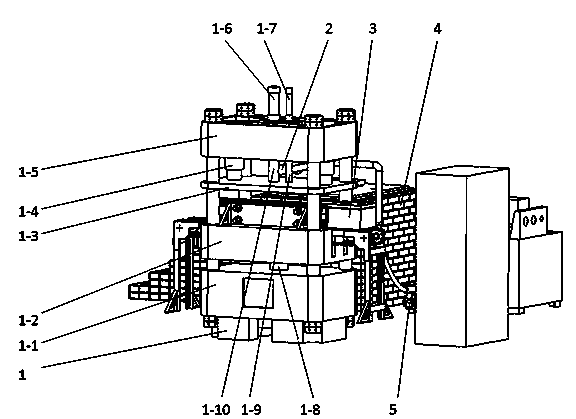
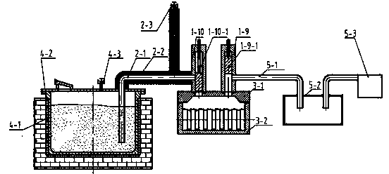
[0041] refer to figure 1 , figure 2 , The vacuum die-casting equipment for metals and their alloys in this embodiment includes a squeeze casting system 1 , a conveying system 2 , a mold 3 , a melting furnace 4 and a vacuum system 5 .

[0042]The squeeze casting system 1 includes a lower beam 1-1, a mold support beam 1-2, a clamping beam 1-3, and an upper beam 1-5 arranged in sequence from bottom to top.

[0043] A lower cylinder 1-8 is arranged between the lower beam 1-1 and the mold support beam 1-2, the lower cylinder 1-8 is located at the center of the lower beam 1-1, and the front end of the piston of the lower cylinder 1-8 is in contact with the mold support beam 1 -2 is connected by flanges and bolts, and the lower cylinder 1-8 serves as the power source for the up and down movement of the mold support beam 1-2.

[0044] Between the mold clamping beam 1-3 and the upper beam 1-5, a vacuum tube 1-9, a material injection tube 1-10 and two mold clamping cylinders 1-4 are ...

Embodiment 2

[0064] The difference between the metal and its alloy vacuum die-casting forming equipment of this embodiment and embodiment 1 is only that: the distance between the feed port and the lower end surface of the injection pipe 1-10 is 200mm, and the two mold clamping cylinders 1-4 are about The centerlines of tubes 1-10 are symmetrical. All the other are with embodiment 1.

[0065] The difference between the vacuum die-casting method for metals and their alloys in this embodiment and that in Embodiment 1 is that the pressing pressure is maintained for 30 minutes. All the other are with embodiment 1.

Embodiment 3

[0067] The difference between the metal and its alloy vacuum die-casting equipment of this embodiment and the first embodiment is that the distance between the feed port and the lower end surface of the injection pipe 1-10 is 400mm, and the rest are the same as the first embodiment.

[0068] The difference between the vacuum die-casting method for metals and their alloys in this embodiment and that in Embodiment 1 is that the pressing pressure is maintained for 50 minutes. All the other are with embodiment 1.


PUM


Abstract

Disclosed is a metal and alloy vacuum die casting forming device and method. The metal and alloy vacuum die casting forming device comprises an extrusion casting system, a conveying system, a die and a melting furnace; the melting furnace is connected with the conveying system; the conveying system is connected with the extrusion casting system; the extrusion casting system is connected with the die; the metal and alloy vacuum die casting forming device is provided with a vacuum pumping system which is connected with the extrusion casting system; the extrusion casting system comprises a lower beam, a die supporting beam, a die clamping beam and an upper beam which are arranged from bottom to top in turn; a lower cylinder is arranged between the lower beam and the die supporting beam; the lower cylinder is located in the center of the lower beam; the front end of a piston of the lower cylinder is connected with the die supporting beam. According to the metal and alloy vacuum die casting forming device and method, the composite effect is good and an air hole, shrinkage porosity and shrinkage cavity can be avoided.

Description

technical field [0001] The invention relates to the field of material processing, in particular to a metal and its alloy vacuum die-casting forming equipment and method. Background technique [0002] Squeeze casting, also known as liquid die forging, is a metal forming technology between casting and die forging. Squeeze casting is to pour a certain amount of liquid or semi-solid metal (hereinafter referred to as molten metal) directly into the die, cooperate with the punch to close the cavity, and apply mechanical static pressure on the punch to fill the entire cavity with the molten metal ; And then the liquid metal crystallization, solidification and a small amount of plastic deformation under pressure. [0003] Compared with casting, squeeze casting can avoid the shrinkage cavity and porosity of the parts, thereby refining the grains and improving the strength of the parts; compared with die forging, squeeze casting can simplify the forming process and reduce the forming...

Claims


Application Information

Patent Timeline
Patent Type & Authority Applications(China)
IPC IPC(8): B22D18/02B22D18/06
CPCB22D18/02B22D18/06
Inventor 吴治华罗俊刘可启娄阳余英洪
Owner HUNAN HANGTIAN CHENGYUAN PRECISION MACHINERY
Why Eureka
Try Eureka