
Turbine blade laser cutting system based on machine vision and industrial robot

An industrial robot and laser cutting technology, applied to laser welding equipment, manipulators, manufacturing tools, etc., can solve the problems of large damage to optical devices, high environmental requirements, and affecting work efficiency, etc., to achieve low cost, ensure operating efficiency, reduce The effect of data

Inactive Publication Date: 2015-01-07
HOHAI UNIV CHANGZHOU
View PDF6 Cites 27 Cited by
  • Summary
  • Abstract
  • Description
  • Claims
  • Application Information

AI Technical Summary

Problems solved by technology

However, for a cutting system that only needs to ensure a cutting margin of 3 to 8 mm, the accuracy of the laser vision system has little impact on the subsequent processes of blade processing but requires a large cost
In addition, the laser light emitted by the laser sensor needs to pass through optical elements such as cylindrical lenses, polarizers, and optical filters to obtain light of a specific wavelength and undergo filtering, noise removal, etc., and finally enter the camera for imaging. The whole process not only has high environmental requirements but also A large amount of data, optics and image processing are required to affect work efficiency
Moreover, long-term laser cutting will cause greater damage to optical devices and increase costs.

Method used


Image

  • Turbine blade laser cutting system based on machine vision and industrial robot
  • Turbine blade laser cutting system based on machine vision and industrial robot
  • Turbine blade laser cutting system based on machine vision and industrial robot

Examples


Embodiment Construction

[0018] The present invention will now be described in further detail in conjunction with the accompanying drawings and preferred embodiments. These drawings are all simplified schematic diagrams, and only illustrate the basic structure of the present invention in a schematic manner, so they only show the configurations related to the present invention.

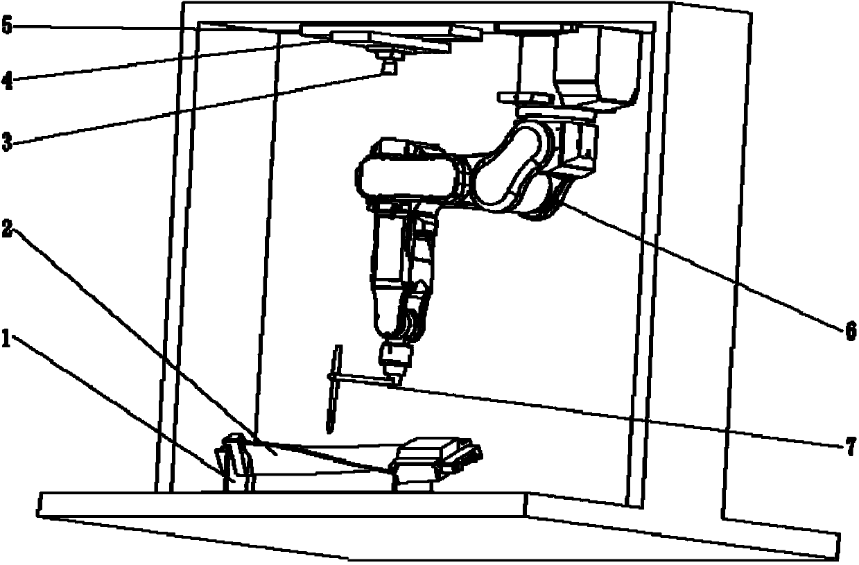
[0019] like figure 1 As shown, a laser cutting system for turbine blades based on machine vision and industrial robots includes an industrial computer, a gantry mechanical platform, an industrial robot with a laser cutter at the end, an image acquisition module, and a multi-axis motion control module; the gantry mechanical A blade fixture is arranged on the platform, and a turbine blade blank is clamped on the blade fixture.

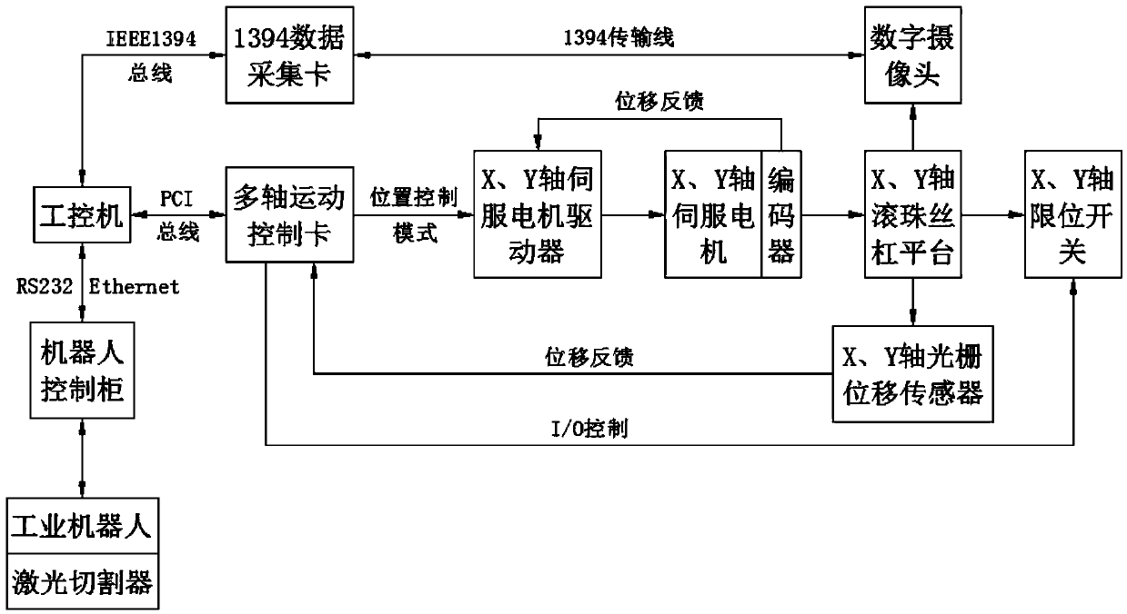
[0020] figure 2 Shown is the block diagram of the working principle of the present invention: among the figure, the industrial computer controls the multi-axis motion control card through the PCI bus ...


PUM


Abstract

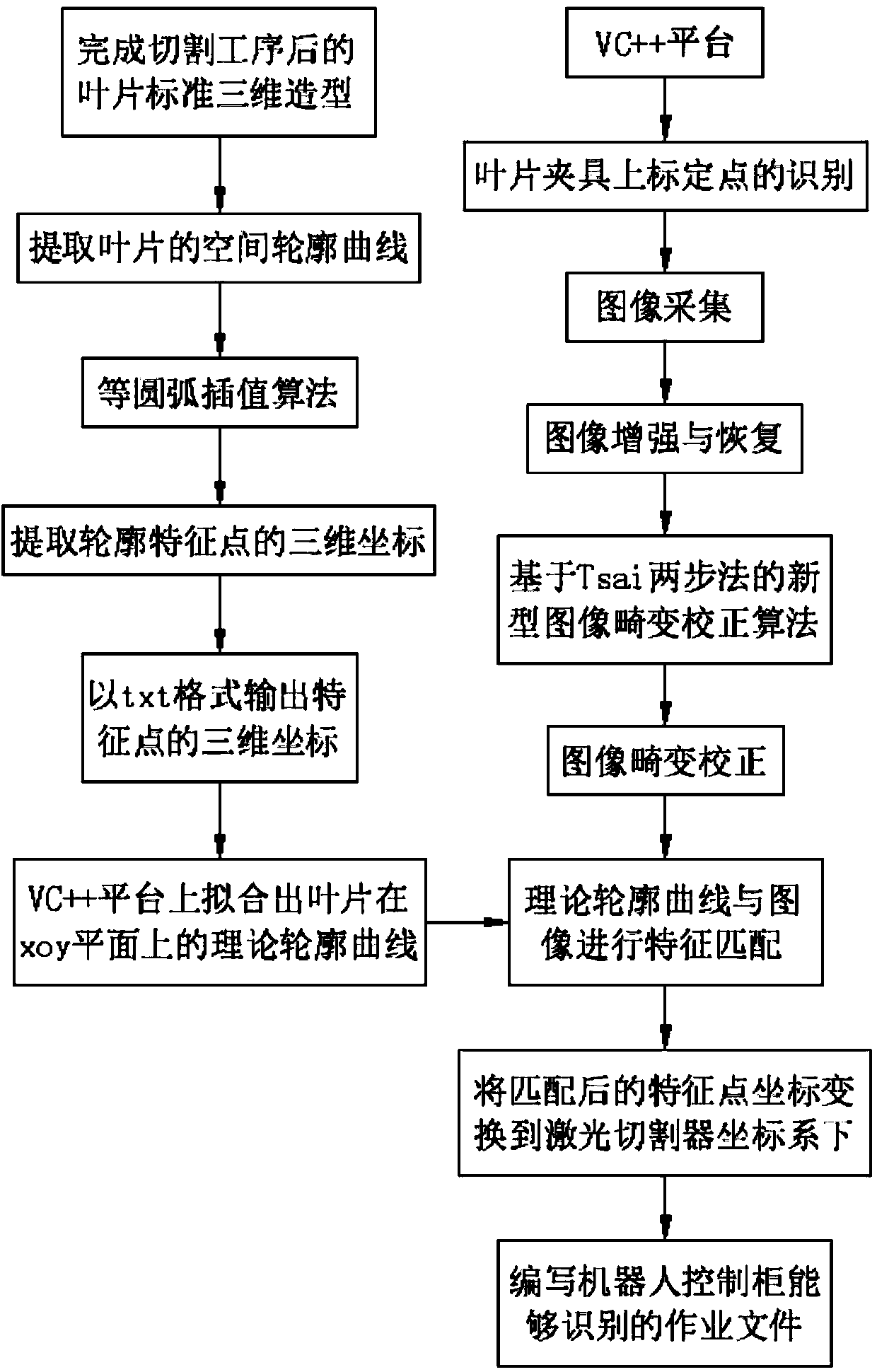
The invention relates to a turbine blade laser cutting system based on machine vision and an industrial robot. The turbine blade laser cutting system comprises an industrial personal computer, a gantry type mechanical platform, the industrial robot loaded with a laser cutter at the tail end, an image acquiring module and a multi-shaft movement control module. A cutting path of a whole blade can be once obtained through matching image information of a blade to be cut with a theoretical profile curve of the blade, so that the efficiency is largely improved, and the matching precision is about 1 mm; a multi-shaft movement control card is used for driving a ball screw platform loaded with a camera to move; and the optimal image information of the blade to be cut is quickly obtained through identifying a fixed point on a blade fixture without needing to obtain the image information in real time like laser vision sensing, so that most data, optimal and image treatment operations are reduced, the operation efficiency is guaranteed, the damage of the camera in the laser cutting process is relieved, the requirement on the operation environment is lower, and the cost is lower.

Description

technical field [0001] The invention relates to the field of machine vision and laser cutting of industrial robots, in particular to a method of using machine vision to obtain the image information of a turbine blade to be cut and match it with the theoretical contour curve after the cutting process is completed, so as to realize the industrial robot driving the laser cutter for cutting system of work. Background technique [0002] Turbine blades are spatial profiles designed through complex numerical calculations based on aerodynamics and fluid mechanics, and their accuracy directly affects the energy conversion efficiency of the equipment. The cutting quality and efficiency of blade blanks are the key to ensure the accuracy and efficiency of subsequent semi-finishing, finishing, polishing and testing processes. At present, the commonly used blade laser cutting methods include teaching reproduction robot cutting and laser vision sensing. [0003] Teaching and reproducing ...

Claims


Application Information

Patent Timeline
IPC IPC(8): B23K26/38B23K26/03B23K26/70
CPCB23K26/032B23K26/38B25J9/1697
Inventor 周军梁齐龙廖华丽傅昱平邵冰冰高海明李超
Owner HOHAI UNIV CHANGZHOU
Learn More