
Skid resistance device for fractured rock mass and construction method thereof

A construction method and rock mass technology, applied in excavation, foundation structure engineering, climate change adaptation, etc., can solve the problems of increasing the time consumption of pile body work, limited ability to resist landslides, and endangering the safety of reinforcement projects, etc. The effect of wide range of conditions, not easy to deteriorate, and safe and easy construction

Active Publication Date: 2015-01-07
ZHONGSHUI FANGYUAN BEIJING ENG CONSULTING +2
View PDF9 Cites 3 Cited by
  • Summary
  • Abstract
  • Description
  • Claims
  • Application Information

AI Technical Summary

Problems solved by technology

This method has many quality control links and many risk factors, which affect the reinforcement effect and even endanger the safety of the reinforcement project in severe cases.
[0004] The reinforcement mechanism of the anti-slide pile is to rely on the bending and shear strength of the pile itself to resist the landslide thrust. This component fails to give full play to the superior performance of the concrete compressive strength of the pile body material, so the ability to resist landslides is limited, and with the increase of the landslide thrust Large, the pile body near the sliding surface is prone to cracking, resulting in failure of the anti-slide pile
In addition, in order to improve the bending and shearing strength, it is time-consuming to increase the work consumables of the cross-sectional area of ​​the pile body.

Method used


Image

  • Skid resistance device for fractured rock mass and construction method thereof
  • Skid resistance device for fractured rock mass and construction method thereof
  • Skid resistance device for fractured rock mass and construction method thereof

Examples


Embodiment Construction

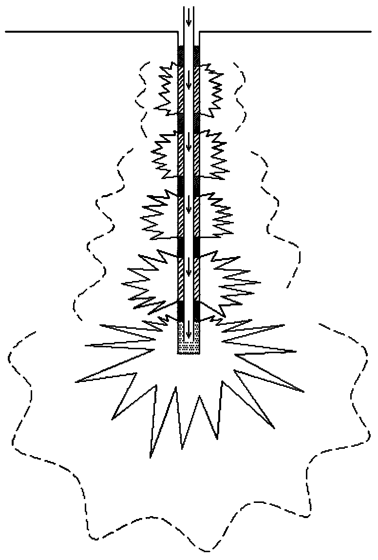
[0022] Such as Figure 5 As shown, the anti-slide device for broken rock mass includes a plurality of grouted anti-slide piles, each grouted anti-slide pile includes a tower-shaped stone column 1, and a shear assembly 2, and the shear assembly includes a seamless steel pipe 3 and the high-strength shear steel column 4, the bedrock 5 is below the broken rock mass 6, the seamless steel pipe 3 is inserted into the bedrock 5 through the broken rock mass 6, the high-strength shear steel column 4 is attached to the seamless steel tube 3, and the high-strength anti-shear A part of the shear steel column 4 is in the bedrock 5 and the other part is in the broken rock mass 6. The tower-shaped stone column 1 formed by multi-stage filling compaction grouting is partly exposed in the broken rock mass or completely in the broken rock mass. in the rock mass.

[0023] Since the shear assembly of the present invention can increase the shear strength of each grouted anti-slide pile, thereby im...


PUM


Abstract

The invention discloses a skid resistance device for fractured rock mass. The stability of an entire slope is improved by improving the shear strength of the device, the material consumption and the time consumption for piling are low, the device is unlikely to crack per se, the application condition is wide, the landslip state is unlikely to deteriorate, and the construction is safe, easy and convenient. The skid resistance device for the fractured rock mass comprises a plurality of grouting anti-skid piles, wherein each grouting anti-skid pile comprises a tower-section stone column and an anti-shear component; the anti-shear component comprises a seamless steel pipe and a high-strength anti-shear steel column; base rock is positioned below the fractured rock mass; the seamless steel pipe is inserted into the base rock through the fractured rock mass; the high-strength anti-shear steel column is attached to the seamless steel pipe; a part of the high-strength anti-shear steel column is positioned in the base rock, and the other part of the high-strength anti-shear steel column is positioned in the fractured rock mass; the tower-section stone column formed through multi-section filling, compacting and grouting is partially exposed out of the fractured rock mass or is completely positioned in the fractured rock mass. The invention also provides a construction method of the skid resistance device.

Description

technical field [0001] The invention belongs to the technical field of water conservancy and hydropower engineering, and in particular relates to an anti-skid device for broken rock mass and a construction method of the anti-skid device, which are mainly used for dam foundation and slope reinforcement, foundation treatment, and landslide body reinforcement. Background technique [0002] After many years of theoretical research and engineering practice, the method of slope treatment has made considerable progress. Among them, the development and application of retaining anti-sliding structures is particularly rapid. Anti-sliding piles (including ordinary anti-sliding piles and prestressed anchor cable anti-sliding piles), The extensive application of new pile-anchor structures such as prestressed anchor cable ground beams (including single beams and frame beams) in engineering practice has greatly improved the efficiency of landslide control. [0003] The prestressed anchor c...

Claims


Application Information

Patent Timeline
Patent Type & Authority Applications(China)
IPC IPC(8): E02D17/20
CPCE02D17/20Y02A10/23
Inventor 吴梦喜
Owner ZHONGSHUI FANGYUAN BEIJING ENG CONSULTING
Learn More