An electrically heated planar cathode

A flat cathode, thermal expansion coefficient technology, applied in the direction of discharge tube solid thermionic cathode, discharge tube main electrode, X-ray tube electrode, etc.

Active Publication Date: 2015-01-07
THERMO SCI PORTABLE ANALYTICAL INSTR INC
View PDF3 Cites 1 Cited by
  • Summary
  • Abstract
  • Description
  • Claims
  • Application Information

AI Technical Summary

Problems solved by technology

This makes it very difficult to focus these electrons into a tight spot on an x-ray target

Method used


Image

  • An electrically heated planar cathode
  • An electrically heated planar cathode
  • An electrically heated planar cathode

Examples


Embodiment Construction

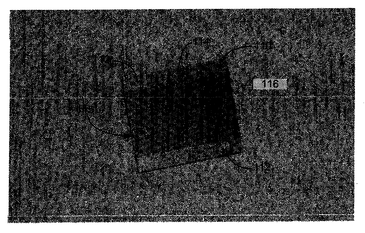
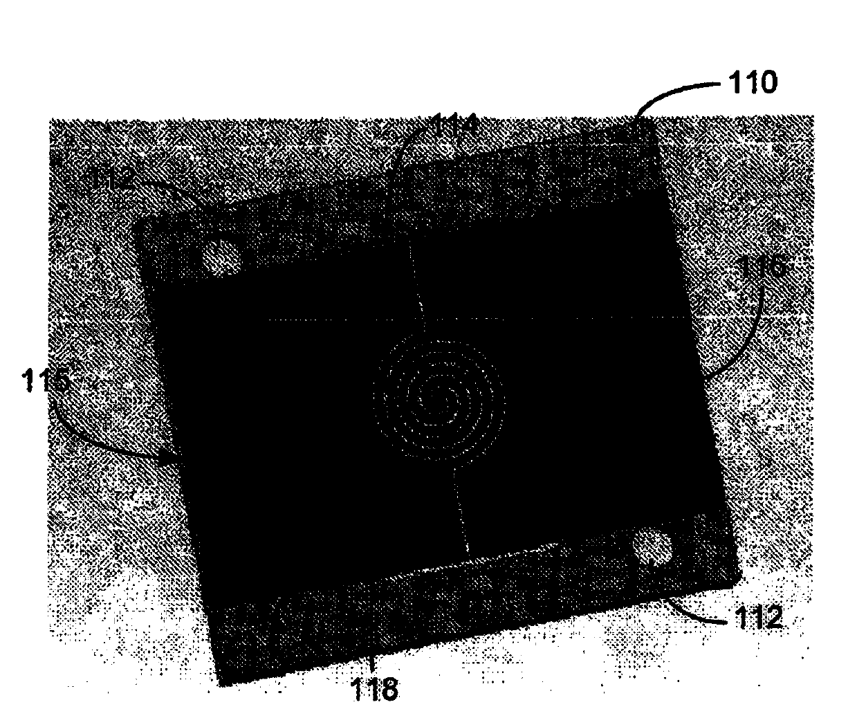
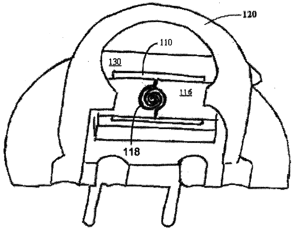
[0006] An electrically heated planar cathode for small X-ray tubes includes a spiral design laser-cut from a thin ribbon foil of tantalum alloy, which has particle-stabilizing properties. The bare ribbon is brazed to an aluminum nitride substrate in such a way that the ribbon is placed in minimal tension before being machined into a geometric pattern such as a helix. This prevents distortion of the planar figure by the cutting process or by handling and mounting. The spiral pattern can be optimized for electrical and thermal properties. The resulting cathode assembly is mounted to a header (sometimes referred to as a "first substrate") for mechanical and electrical connection to the rest of the X-ray tube assembly. The remainder of the tantalum ribbon on the outside of the cathode spiral forms an equipotential surface that contributes to a very collimated and easily focussable electron beam.

[0007] This particular implementation addresses the fragility of such a structure ...


PUM


Abstract

An electrically heated planar cathode for use in miniature x-ray tubes may be spiral design laser cut from a thin tantalum alloy ribbon foil (with grain stabilizing features). Bare ribbon is mounted to an aluminum nitride substrate in a manner that is puts the ribbon in minimal tension before it is machined into the spiral pattern. The spiral pattern can be optimized for electrical, thermal, and emission characteristics.

Description

Background technique [0001] An X-ray tube is a vacuum tube that produces X-rays. The X-ray tube includes a cathode for emitting electrons into the vacuum and an anode for collecting electrons. A high voltage power supply is connected across the cathode and anode to accelerate electrons. Some applications require very high resolution images and require X-ray tubes capable of producing very small focal spot sizes. [0002] One type of cathode consists of a tungsten filament that is helically wound into a spiral, similar to the filament of a light bulb. The problem with this wound wire is that the electrons are emitted from surfaces that are not perpendicular to the accelerating electric field. This makes it very difficult to focus these electrons into a tight spot on an X-ray target. Contents of the invention [0003] An electrically heated planar cathode for use in small X-ray tubes consists of a helical design made from a foil, such as a thin strip of tantalum alloy (whi...

Claims


Application Information

Patent Timeline
Patent Type & Authority Applications(China)
IPC IPC(8): H01J35/06
CPCH01J35/06H01J2235/06H01J1/15H01J35/14H01J35/147H01J35/064Y10T29/49208
Inventor D·J·卡鲁索M·T·丁斯莫尔
Owner THERMO SCI PORTABLE ANALYTICAL INSTR INC
Why Eureka
Try Eureka