Optical sub-module detecting machine and detecting method

A technology of optical sub-module and inspection machine, which is applied in the direction of optical instrument testing, measuring device, machine/structural component testing, etc. It can solve the quality error of optical sub-module finished product inspection, the quality of finished product cannot be accurately grasped, and the efficiency of semi-automatic inspection is low, etc. problems, to achieve the effect of reducing testing costs, shortening the waiting time for testing, and saving labor costs

Inactive Publication Date: 2015-01-14
WUHAN YIKE SIDE TECH
View PDF17 Cites 44 Cited by
  • Summary
  • Abstract
  • Description
  • Claims
  • Application Information

AI Technical Summary

Problems solved by technology

[0003] The traditional detection method of the optical sub-module generally adopts pure manual detection or semi-automatic detection with the help of a machine. In several ways, there are many variables that may affect the detection results. The error of finished product inspection quality leads to the inability to accurately grasp the quality of finished products, so that the qualified rate cannot be improved, and the cost is relatively increased; moreover, the efficiency of manual inspection and semi-automatic inspection is low, and the inspection cost is high, which is not conducive to mass inspection

Method used


Image

  • Optical sub-module detecting machine and detecting method
  • Optical sub-module detecting machine and detecting method
  • Optical sub-module detecting machine and detecting method

Examples


Embodiment Construction

[0066] In order to understand the purpose, features and advantages of the present invention more clearly, the following describes the embodiments of the present invention in detail by taking the light emitting sub-module as an example and in conjunction with the accompanying drawings, but the protection scope of the present invention is not limited to the following embodiments.

[0067] In an embodiment of the present invention, the aforementioned mechanism components can be implemented by the following structure:

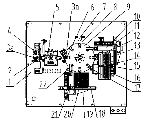
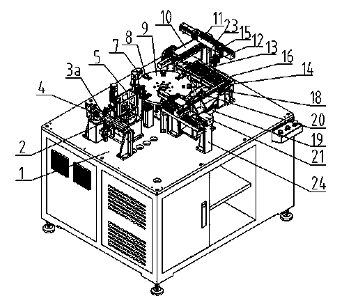
[0068] Such as figure 1 , 5 , 10, the fiber end face detection cleaning and fiber insertion coupling mechanism adopts the fiber head cleaning mechanism 2, the fiber head clamping mechanism 3a (3b), the fiber head end face cleanliness detection lens 4, the rotating frame 5, the guide clamp finger 6, The electrical signal transmission probe 25 is specifically implemented.

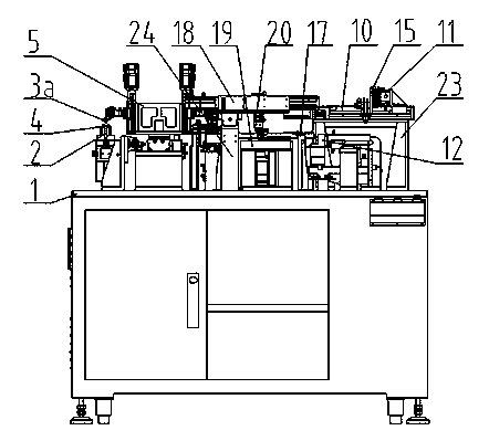
[0069] Such as figure 1 , 2 , 3, 4, and 6, the feeding mechanism components adopt X-direction linear ...


PUM


Abstract

The invention provides an optical sub-module detecting machine and detecting method. Through the detecting machine, optical sub-modules which include but are not limited to an optical transmitting sub-module and an optical receiving sub-module are fully automatically fed and detected, and good and bad products can be respectively discharged. The detecting machine comprises an optical fiber end face detecting and cleaning and optical fiber inserting and coupling mechanism, a full-automatic feeding mechanism, a feeding mechanism assembly, a discharging mechanism assembly, a high-accuracy station transferring mechanism (such as a rotating mechanism and a linear reciprocating conveying mechanism), a workbench, a control panel, a closed loop automatic detection control system, a human-machine conversion interface, a protecting cover and a fault alarming system. The optical sub-module detecting machine and detecting method make up for the blank in the field of full-automatic detection of optical sub-modules, and solve the problems that because of manual detection or semi-automatic detection, the detecting accuracy of parts to be detected is not high, the detecting efficiency is low, and the detecting cost is high.

Description

Technical field [0001] The invention relates to the field of automatic detection of intelligent industrial robots, in particular to an optical sub-module detection machine and a detection method. Background technique [0002] In optoelectronic transmission, the optical sub-modules of the optical fiber transmitter can be divided into sub-modules and light-receiving sub-modules according to the different functional components. Among them, the optical emission sub-module is used to provide functional components to the optical fiber, such as semiconductor laser to optical fiber or light emitting diode to optical fiber , Which converts electrical signals into light and focuses on the optical fiber through a lens for transmission. [0003] The traditional detection methods of optical sub-modules generally use pure manual detection or semi-automatic detection with the help of machines. In several ways, there are potentially many variables that affect the detection results, such as: the ...

Claims


Application Information

Patent Timeline
Patent Type & Authority Applications(China)
IPC IPC(8): G01M11/00
Inventor 杨戬李亚林鄢炜臻张伟林卫国
Owner WUHAN YIKE SIDE TECH
Why Eureka
Try Eureka