Oil pumping unit at mouth of well

A pumping unit and sucker rod technology, which is applied in wellbore/well components, production fluids, earth-moving drilling, etc., can solve problems such as low belt transmission efficiency, achieve safe and reliable motor operation, overcome difficulties in parameter adjustment, and reduce The effect of small energy loss

Inactive Publication Date: 2015-01-21
PETROCHINA CO LTD
View PDF7 Cites 2 Cited by
  • Summary
  • Abstract
  • Description
  • Claims
  • Application Information

AI Technical Summary

Problems solved by technology

[0009] The purpose of the present invention is to overcome the low efficiency of the belt drive of the existing pumping unit and the above-mentioned insufficient problems when the three-phase asynchronous motor is used as the power of the pumping unit

Method used


Image

  • Oil pumping unit at mouth of well
  • Oil pumping unit at mouth of well
  • Oil pumping unit at mouth of well

Examples


Embodiment 1

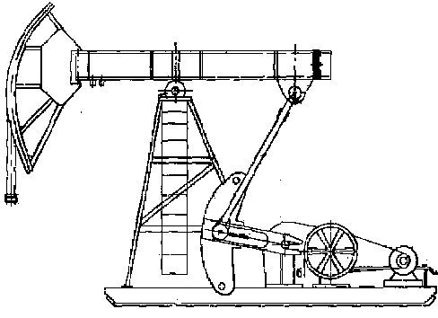
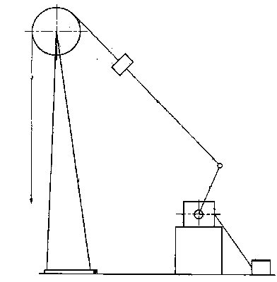
[0030] In order to overcome the low efficiency of the belt drive of the existing pumping unit and the insufficient problems of the three-phase asynchronous motor used as the power of the pumping unit, this embodiment provides a Figure 5 The wellhead pumping unit shown includes a sucker rod 4, a switched reluctance motor 1, a rotary table 2, an eccentric shaft 3 and a motor control box 6;

[0031] One end of the switched reluctance motor 1 is electrically connected to the motor control box 6, and the other end is connected to the turntable 2 through a linkage shaft. The turntable 2 is provided with an eccentric shaft 3, and the sucker rod 4 is connected to the eccentric shaft 3.

[0032] The switched reluctance motor 1 and the turntable 2 are supported on the ground by brackets; the eccentric shaft 3 is flexibly connected to the turntable 2, and the sucker rod 4 realizes different strokes through different suspension positions on the turntable 2. The stopped rotation drives th...

Embodiment 2

[0039] On the basis of Embodiment 1, the motor control box 6 is composed of a microcomputer, an energy-saving control module, and a power converter, and the energy-saving control module and the power converter are respectively electrically connected to the microcomputer. The motor control box 6 is used to control the continuous operation of the switched reluctance motor 1. Its specific working principle is as follows: the microcomputer comprehensively processes the speed command, the speed feedback signal and controls the main switching device in the power converter through the feedback information of the position sensor. On and off to realize the control of the running state of the switched reluctance motor 1 . According to the speed feedback signal, the energy-saving control module runs the intelligent speed regulation algorithm, analyzes and calculates the optimal operation, forms a control strategy, and generates operation instructions. The power converter controls the swi...


PUM


Abstract

The invention belongs to the technical field of mechanical equipment for oil extraction in oil fields, and particularly provides an oil pumping unit at the mouth of a well. The oil pumping unit comprises a pumping rod as well as a switch reluctance machine, a speed reducer, a rotary disk, an eccentric shaft and a motor control cabinet, wherein one end of the switch reluctance machine is electrically connected with the motor control cabinet, and the other end thereof is connected with the rotary disk through a universal driving shaft; the eccentric shaft is arranged on the rotary disk; the pumping rod is connected with the eccentric shaft. By utilizing the advantages of the switch reluctance machine, the oil pumping unit at the mouth of the well removes belt drive and reduces the power transmission link to improve the transmission efficiency, and eliminates insufficient power when a three-phase asynchronous motor is used as an oil pumping unit, so as to achieve the purposes of energy conservation and consumption reduction.

Description

technical field [0001] The invention belongs to the technical field of oil production mechanical equipment in oil fields, and in particular relates to a wellhead pumping unit. Background technique [0002] The pumping unit is the ground-driven equipment of the rod pumping system. According to its basic structure, the existing pumping units can be divided into two categories: beam pumping and beamless. The beam pumping unit is mainly composed of four parts: beam-connecting rod-crank mechanism, deceleration mechanism, power equipment and auxiliary devices, such as figure 1 The beamless pumping unit is a pumping unit that replaces the beam with other methods such as flexible parts, such as figure 2 Show. [0003] Regardless of whether it is a beam pumping unit or a beam pumping unit without a beam, it is driven by a belt. The belt and the reducer together constitute the reduction transmission device of the pumping unit to realize the power transmission and deceleration from ...

Claims


Application Information

Patent Timeline
Patent Type & Authority Applications(China)
IPC IPC(8): E21B43/00
CPCE21B43/121
Inventor 韩二涛李明甘庆明曾亚勤黄伟辛宏张磊杨海涛刘天宇
Owner PETROCHINA CO LTD
Why Eureka
Try Eureka