Magnetic levitation overspeed test bed for impeller overspeed test

A technology of overspeed test and magnetic levitation, applied in pump control, non-variable capacity pump, machine/engine, etc., can solve the problems of low load and life, low motor output speed, difficult to control, etc., to achieve good dynamic balance performance, connection Simple structure and improved resistance

Active Publication Date: 2015-01-21
NANJING CIGU TECH CORP LTD
View PDF4 Cites 11 Cited by
  • Summary
  • Abstract
  • Description
  • Claims
  • Application Information

AI Technical Summary

Problems solved by technology

Because there is a speed difference between the rotor and the stator magnetic field, the rotor speed is unstable and difficult to control, so an additional speed sensor and controller must be used to stabilize the impeller speed, the system is complex, bulky and expensive
[0009] 2. The output speed of the motor is low, so multi-stage speed-up gears or even multiple gearboxes in series are required to reach the predetermined speed
As the number of stages increases, the efficiency of gear transmission decreases, the noise and heat generation increase, the failure rate increases significantly, and even major accidents such as self-locking are prone to occur.
Although the use of synchronous belt transmission can obtain a larger single-stage transmission ratio, its load and life are far lower than that of gear transmission.
Therefore, this type of overspeed test bench has complex structure, high price, low efficiency and reliability
[0010] 3. The speed adjustment range of asynchronous AC motors is narrow, and the overspeed speeds of different impellers vary greatly. Therefore, there are only two options for this type of overspeed test bench to be compatible with more impellers: using a complex variable speed gearbox, or according to different impellers. Change to a different gearbox
The former option is convenient to operate but increases the price; the latter option increases the workload of the experiment
[0011] 4. Due to the use of sliding bearings, oil film dampers and the need for high-speed gearbox lubrication, a special lubrication system must be equipped, which not only increases the complexity of the system, but also cannot avoid failures such as leakage, leakage, etc.
When the quality of the rotor decreases, a smaller mass offset is required to ensure the same dynamic balance performance; however, the overspeed test bench needs to frequently replace the test impeller, and the consistency of the impeller is difficult to guarantee, so most of the time the dynamic balance performance is poor work without
A lighter rotor means more vibration, and even with a technically difficult oil film damper it is difficult to keep the rotor stable

Method used


Image

  • Magnetic levitation overspeed test bed for impeller overspeed test
  • Magnetic levitation overspeed test bed for impeller overspeed test
  • Magnetic levitation overspeed test bed for impeller overspeed test

Examples


Embodiment Construction

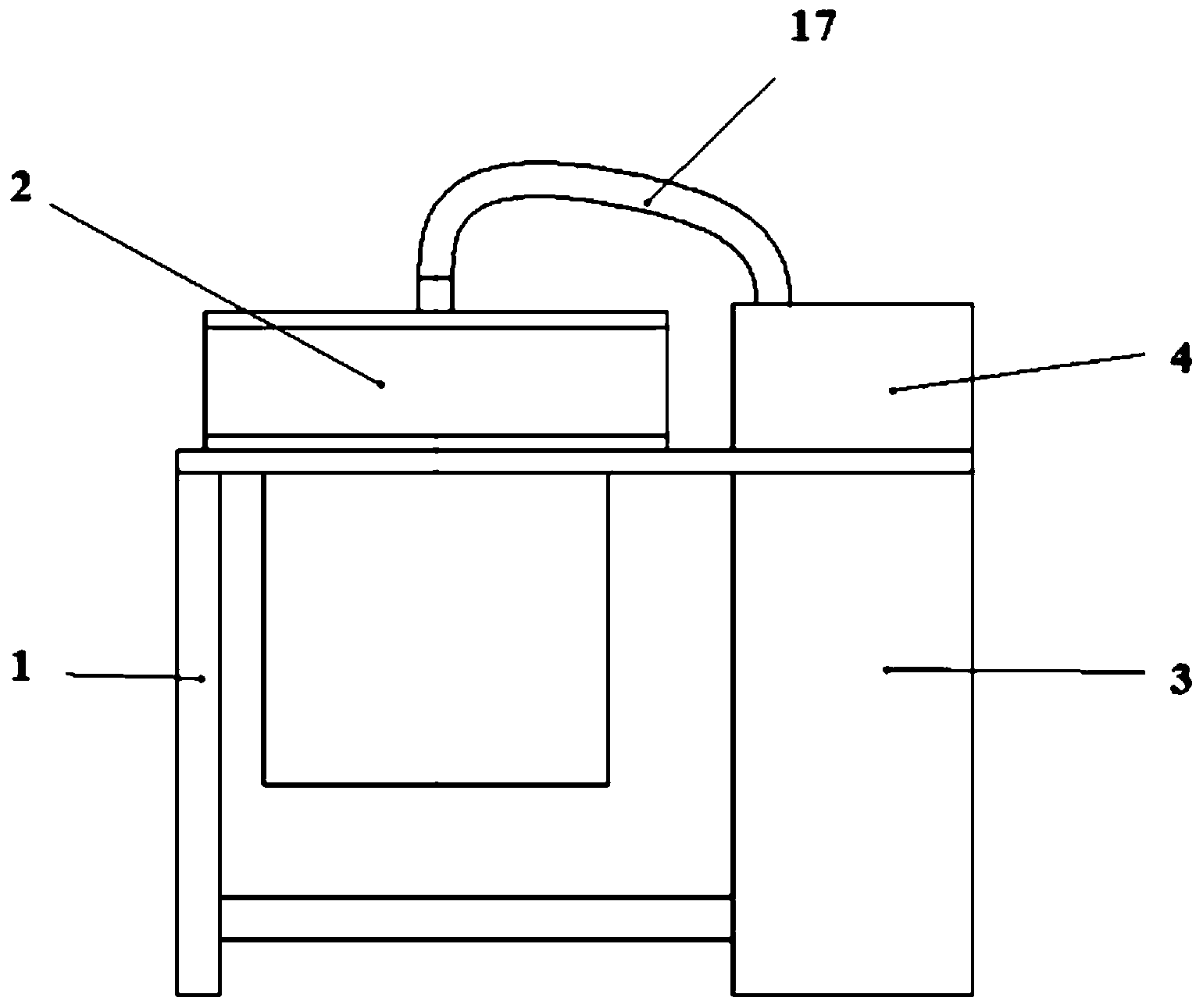
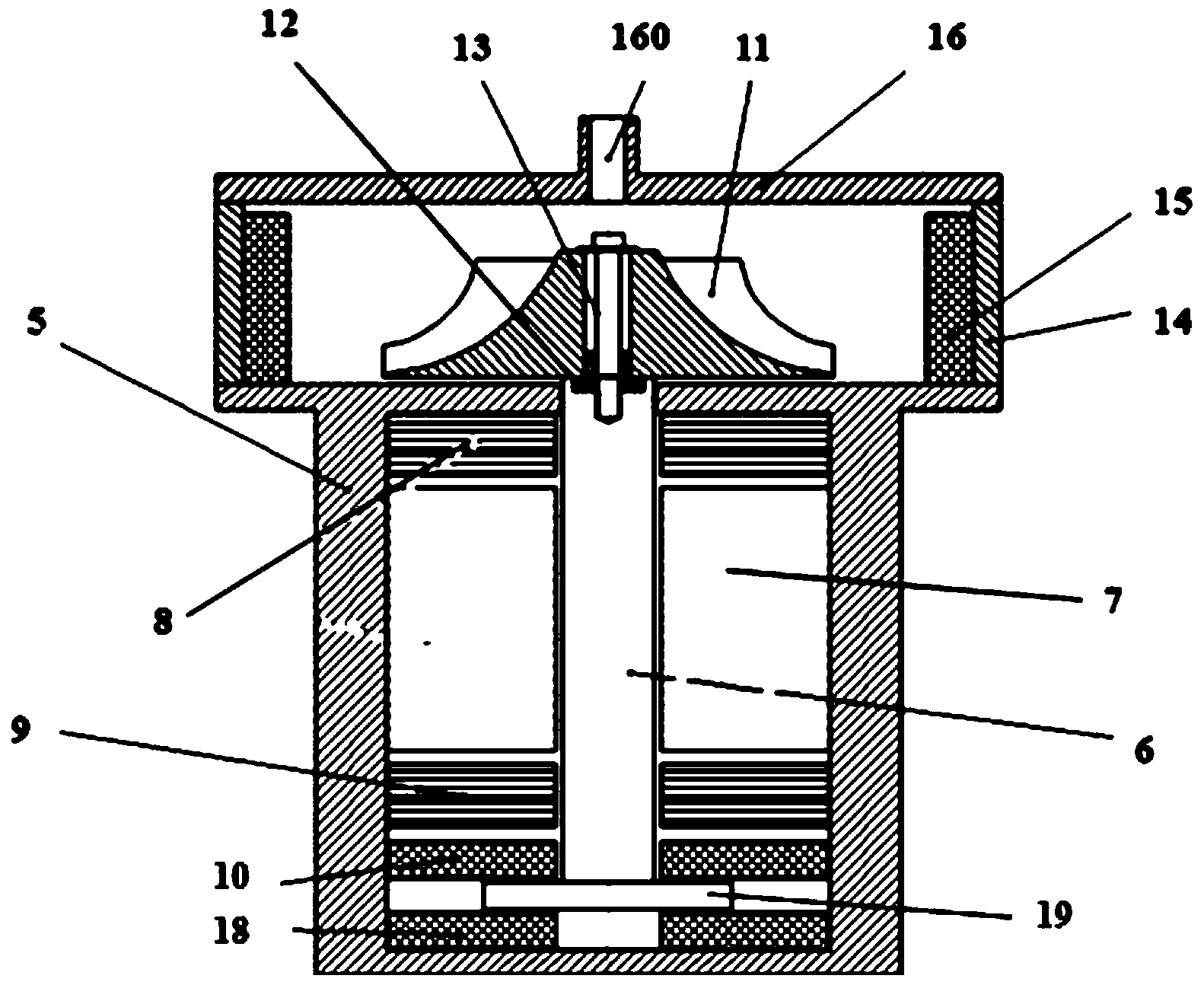
[0038] Please refer to Figure 1 to Figure 3 As shown, the magnetic levitation overspeed test bench for the impeller overspeed test of the present invention includes a support 1 and a host 2 installed on the support 1 , an electric control cabinet 3 and a vacuum pump 4 . The main engine 2 includes a motor housing 5, a motor rotor 6 installed in the motor housing 5, and an electronic stator 7, wherein the upper end of the motor rotor 6 extends beyond the upper end surface of the motor housing 5, and is located on the motor rotor 6. An upper radial magnetic bearing 8 and a lower radial magnetic bearing 9 are installed on the upper and lower positions of the stator 7, and an upper thrust magnetic bearing 10 and a lower thrust magnetic bearing 10 are installed on the motor rotor 7 below the lower radial magnetic bearing 9. The bearing 18 and the disc-shaped thrust disc 19 located between the upper thrust magnetic bearing 10 and the lower thrust magnetic bearing 18, the upper end o...


PUM


Abstract

The invention discloses a magnetic levitation overspeed test bed for an impeller overspeed test. The magnetic levitation overspeed test bed comprises a support, a main machine, an electric control cabinet and a vacuum pump. The main machine, the electric control cabinet and the vacuum pump are installed on the support. The main machine comprises a motor shell, a motor rotor and a motor stator, wherein the motor rotor and the motor stator are installed in the motor shell. The upper tail end of the motor rotor extends out of the upper end face of the motor shell. The motor rotor is provided with an upper radial magnetic bearing, a lower radial magnetic bearing, an upper thrust magnetic bearing, a lower thrust magnetic bearing and a thrust disc. The upper tail end of the motor rotor is connected with a safety connector and a pull rod screw which are used for fixing an impeller to the upper end of the motor rotor. A protective cover is arranged at the position, around the impeller, of the motor shell. A protective cover lid is installed on the protective cover. The upper surface of the motor shell, the protective cover and the protective cover lid jointly form a closed contained wrapping the impeller. A buffer block is installed on the inner wall of the protective cover. A vacuumizing connector is formed on the protective cover lid. A vacuumizing pipe is installed on the vacuumizing connector. The other end of the vacuumizing pipe is connected to the vacuum pump.

Description

Technical field: [0001] The invention relates to a testing device for an impeller overspeed test, in particular to a magnetic levitation overspeed test bench for an impeller overspeed test. Background technique: [0002] Most of the traditional centrifugal fans are used for local overspeed, that is, using the original main engine of the fan to achieve the speed required for the overspeed test by slightly increasing the speed. However, this test method requires a high safety margin (at least 30%) in the overall structure of the fan, and the performance waste is also large during actual work; at the same time, once an accident such as impeller breakage occurs in the test, the entire fan will be scrapped, and the test personnel security is also difficult to guarantee. Therefore, some enterprises refit the fans into special overspeed test benches for overspeed tests. At present, the typical technical scheme of domestic overspeed test bench is as follows: [0003] 1. Use ordin...

Claims


Application Information

Patent Timeline
Patent Type & Authority Applications(China)
IPC IPC(8): F04D27/00
CPCF04D27/001
Inventor 胡思宁丁嵩李健吴立华董继勇
Owner NANJING CIGU TECH CORP LTD
Why Eureka
Try Eureka