
Precise micro-dynamic parallel locating system and method for micro-nano operation environment

An operating environment and positioning system technology, which is applied in the fields of precision measurement, precision positioning, and precision manufacturing, can solve problems such as assembly errors of parallel mechanism branch chains, decrease in stiffness and load-bearing capacity, and influence on mechanism positioning accuracy, etc., to achieve the elimination of rotary joints Clearance, fast response, and guaranteed accuracy

Active Publication Date: 2015-01-28
SOUTH CHINA UNIV OF TECH
View PDF7 Cites 37 Cited by
  • Summary
  • Abstract
  • Description
  • Claims
  • Application Information

AI Technical Summary

Problems solved by technology

The disadvantage of this scheme is that the rigidity and load-bearing capacity of the mechanism are reduced, and vibration is easily generated during high-speed positioning movement
[0008] In addition, none of the mechanisms mentioned above and the literature that has been checked so far have considered eliminating the assembly error of the branch chain of the parallel mechanism
For parallel mechanisms, especially planar parallel mechanisms, the assembly error of each branch chain will cause the tilt or deformation of the moving platform, which will affect the positioning accuracy of the mechanism

Method used


Image

  • Precise micro-dynamic parallel locating system and method for micro-nano operation environment
  • Precise micro-dynamic parallel locating system and method for micro-nano operation environment
  • Precise micro-dynamic parallel locating system and method for micro-nano operation environment

Examples


Embodiment Construction

[0074] Hereinafter, the present invention will be further described in detail with reference to the examples and drawings, but the implementation of the present invention is not limited thereto.

[0075] In the accompanying drawings:

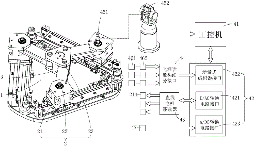
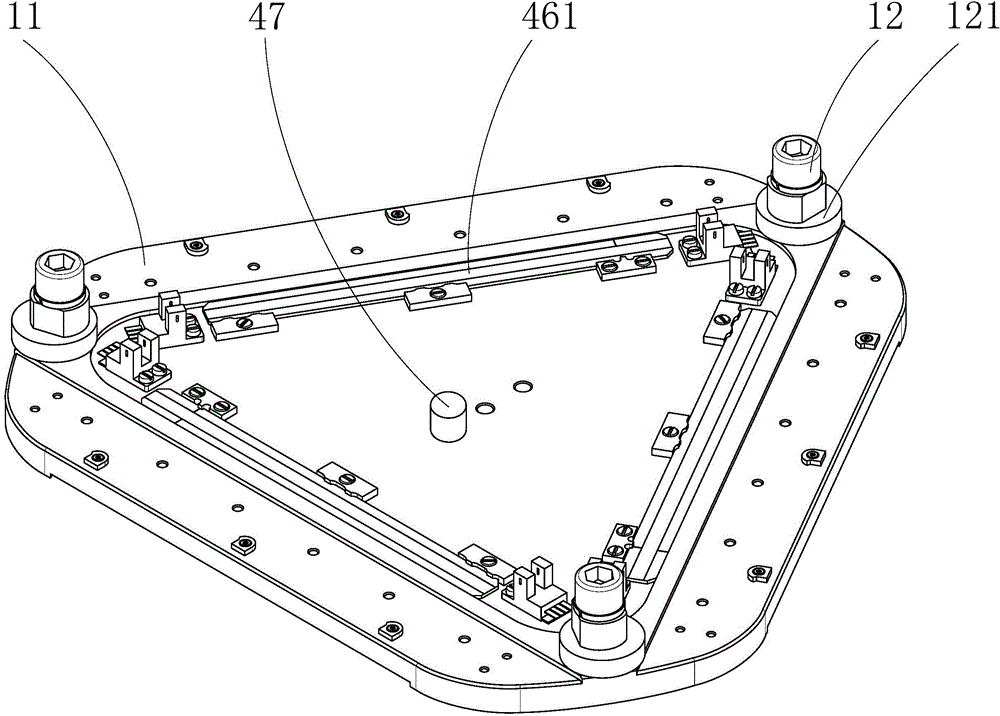
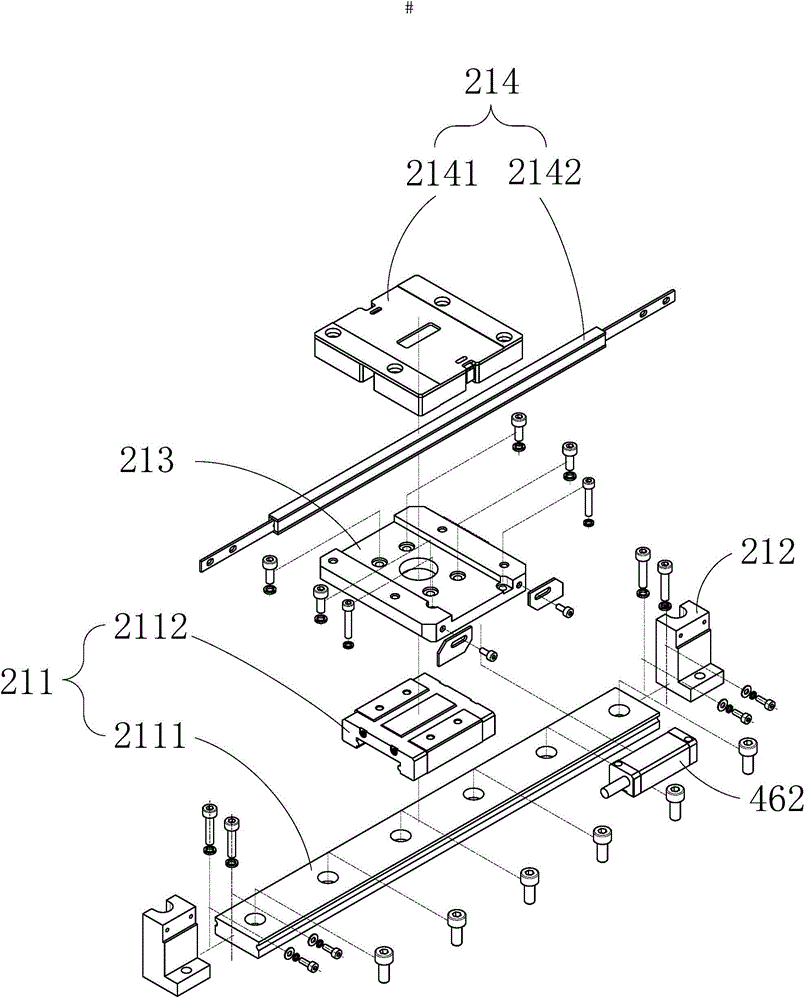
[0076] 1-Base; 11-Bottom plate; 12-Eccentric wheel clamping mechanism; 121-Eccentric wheel column; 2-Ultrasonic motor drive branch chain; 21-Active moving joint; 211-Rolling linear bearing; 2111-guide rail; 2112-slide Block; 212-motor fixing bracket; 213-connecting plate; 214-linear ultrasonic motor; 2141-base body; 2142-guide rod; 22-passive rotating joint I; 221-joint frame; 222-rotating shaft I, 223-precision Bearing Ⅰ; 224-precision bearing Ⅱ; 225-lock nut Ⅰ; 226-elastic deformation part; 227-press plate; 23-passive rotating joint Ⅱ; 231-connecting rod; 232-precision bearing Ⅲ; 233-precision bearing Ⅳ 234-Rotary shaft Ⅱ; 235-end cover; 236-lock nut Ⅱ; 3-moving platform; 41-industrial computer; 42-controller; 421-D / AC conversion circuit; 422-incr...


PUM


Abstract

The invention discloses a precise micro-dynamic parallel locating system and method for micro-nano operation environment. The precise micro-dynamic parallel locating system for the micro-nano operation environment comprises a mechanical body, a calibrating device and a control device which are connected in sequence; the mechanical body comprises a pedestal, more than three groups of the same ultrasonic motor drive branched chains and a movable platform; the calibrating device is used for calibrating the actual value of a kinematics parameter, feeding back the movement position of a joint and correcting the original point of the movable platform; the control device is used for processing each module signal, processing correspondingly and driving the mechanical body to move according to a scheduled track. The precise micro-dynamic parallel locating system and method avoid the disadvantages of a traditional electromagnetic motor and reduce the influences of such nonlinear factors as friction and elastic deformation of additional mechanisms and gaps between additional mechanisms, and the precise micro-dynamic parallel locating system is gapless, high in intensity, compact in structure, capable of eliminating assembly error and size error and suitable for the micro-nano operation environment; the precise micro-dynamic parallel locating system and method for the micro-nano operation environment can achieve sub-micron locating precision and millimeter travel and can also be used for macro-micro locating tables.

Description

Technical field [0001] The invention relates to the fields of precision manufacturing, precision measurement, and precision positioning, in particular to a precision macro-motion parallel positioning system and method under a micro-nano operation environment. Background technique [0002] With the development of science and technology, precision manufacturing, precision measurement and precision positioning technology occupy an increasingly important position in the forefront of scientific research and industrial production. For example, in the fields of bioengineering, precision mechanical engineering or materials science, it is often necessary to use a micro-nano operating system to study samples. The micro-nano operating system includes an observer, a positioning platform and a manipulator. Existing commercial observers such as scanning electron microscopes (SEM), etc., are equipped with positioning platforms that often use a series structure, which has low accuracy and is eas...

Claims


Application Information

Patent Timeline
IPC IPC(8): G05B19/042B25J9/00
CPCB25J9/00G05B19/042
Inventor 张宪民魏骏杨莫嘉嗣邱志成
Owner SOUTH CHINA UNIV OF TECH
Learn More