Rechargeable lithium ion button cell battery
A button battery and rechargeable lithium technology, applied in secondary batteries, battery pack components, secondary battery manufacturing, etc., can solve problems such as configuration practicability doubts
- Summary
- Abstract
- Description
- Claims
- Application Information
AI Technical Summary
Problems solved by technology
Method used
Image
Examples
example 1
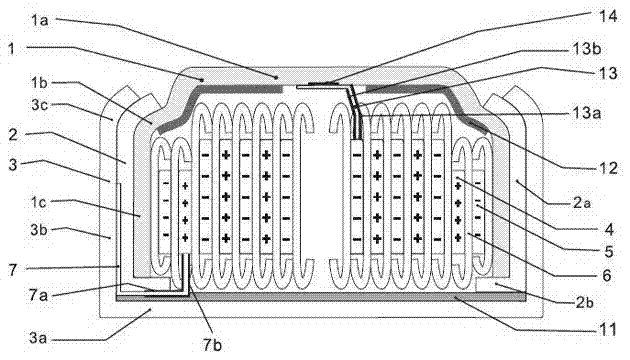
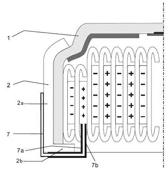
[0081] refer to figure 1 , the inventors of the present invention produced a lithium-ion rechargeable button battery of model Z23 with a diameter of 7.8 mm and a height of 5.3 mm according to the method described above.
[0082] The battery cases 1 and 3 are made of nickel-plated stainless steel, which can be 316, 304 or 430, and its thickness is between 0.1 and 0.15 mm, preferably 0.125 mm. The standing edge 1c of this anode cover is single-layered. The apron 2 is formed by injection molding of polypropylene, with a thickness between 0.06 and 0.15 mm, preferably 0.12 mm.
[0083] The cathode is preferably made of lithium-rich materials such as lithium nickel manganese cobaltate and other additives mixed with NMP as a solvent under vacuum, and the mixed slurry is coated on both sides of the aluminum foil with a thickness of 0.01 to 0.025 mm, preferably 0.012 mm. The coated material is heated and dried and pressed to the required thickness in a counter roll machine, usually ...
example 2
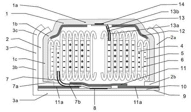
[0090] refer to image 3 , most of the accessories, materials and process flow are similar to Example 1, except that the cathode current collector 7 is pre-welded on a circular aluminum sheet 10, which is usually 0.05 mm thick, such as Figure 5 . The aluminum sheet 10 is pre-attached with an O-shaped insulating pad 11a with a hole in the center. After welding with the current collector 7, another round insulating pad 11 is taken to completely cover the exposed metal part of the welded part. After filling the electrolyte, the metal sheet 10 is folded back and covers the winding core. Finally put on the shell 3 to realize sealing by buckling the edge.
[0091] The performance of the manufactured battery is also similar to that of Example 1, except for the pre-welding process of additional aluminum sheets 10 and conductive tabs 7, which may increase the risk of failure rate. In addition, the 0.05 mm thick aluminum sheet needs to occupy a little more internal space, and the ca...
example 3
[0093] refer to Figure 4 , most of the accessories, materials and process flow are similar to Example 1, except that the cathode current collector 7 is directly welded on the inner plane 3a of the shell. This requires a longer current collector 7, otherwise the ultrasonic welding of the bottom cannot be realized due to the hindrance of the shell standing edge 3b. In order to completely cover the exposed metal in the shell, an O-shaped insulating pad 11a with a hole in the center must be pasted on the inner plane 3a of the shell in advance. After welding with the current collector 7, another round insulating pad 11 is taken as a whole. Cover the exposed metal part of the weld. After liquid injection, the long current collector 7 needs to be bent several times to be inserted into the interior of the battery and complete buckling and sealing.
[0094] The performance of the manufactured battery is also similar to that of Example 1 and Example 2, except for the risk that the lo...
PUM
| Property | Measurement | Unit |
|---|---|---|
| height | aaaaa | aaaaa |
| height | aaaaa | aaaaa |
| diameter | aaaaa | aaaaa |
Abstract
Description
Claims
Application Information
 - R&D
- Intellectual Property
- Life Sciences
- Materials
- Tech Scout
- Unparalleled Data Quality
- Higher Quality Content
- 60% Fewer Hallucinations
Browse by: Latest US Patents, China's latest patents, Technical Efficacy Thesaurus, Application Domain, Technology Topic, Popular Technical Reports.
© 2025 PatSnap. All rights reserved.Legal|Privacy policy|Modern Slavery Act Transparency Statement|Sitemap|About US| Contact US: help@patsnap.com


