Coiling method of oriented silicon steel MgO coated steel coil

A technology for oriented silicon steel and steel coils, applied in furnaces, heat treatment equipment, heat treatment furnaces, etc., which can solve problems such as wrinkles, water cannot be effectively discharged, and waste judgment.

Active Publication Date: 2015-02-11
BAOSHAN IRON & STEEL CO LTD
View PDF8 Cites 7 Cited by
  • Summary
  • Abstract
  • Description
  • Claims
  • Application Information

AI Technical Summary

Problems solved by technology

[0005] (1) In view of the collapse and core-pulling problems of steel coils after high-temperature annealing in the production of FCL units, the decarburization annealing DCL unit will increase 3-5N / mm for steel coils with specifications of 0.30mm-0.23mm 2 The coiling tension mode coiling can not effectively solve the above problems
[0006] (2) The coiling tension of the DCL unit should not be excessively increased, such as the coiling tension is too large (>80N / mm 2 ) will cause the gap between the DCL outlet roll layer and the layer to be too small, and the water in the MgO coating cannot be effectively discharged during high temperature annealing. Indentation" and other surface quality defects, resulting in product degradation or even scrap
[0007] (3) When the inner and outer rings of the steel coil deviate from the core, the quality of the inner and outer rings of the steel coil will be seriously damaged, and the strip will have defects such as creases, wrinkles, and scroll marks, and the strip will not be released as a finished product. The quality cost of silicon steel is greatly lost
This patent is the control system of the aluminum foil coating production line. Its core content is the coiling tension control system. The winding machine is driven by the variable frequency motor with frequency converter to realize the tension control of the coiling system, and the relevant coiling is not involved. Specific parameters of tension

Method used


Image

  • Coiling method of oriented silicon steel MgO coated steel coil
  • Coiling method of oriented silicon steel MgO coated steel coil
  • Coiling method of oriented silicon steel MgO coated steel coil

Examples


Embodiment 1-9

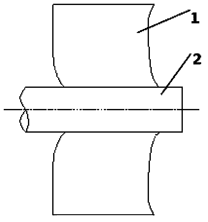
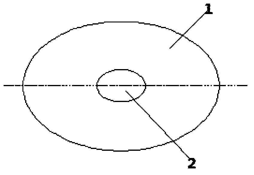
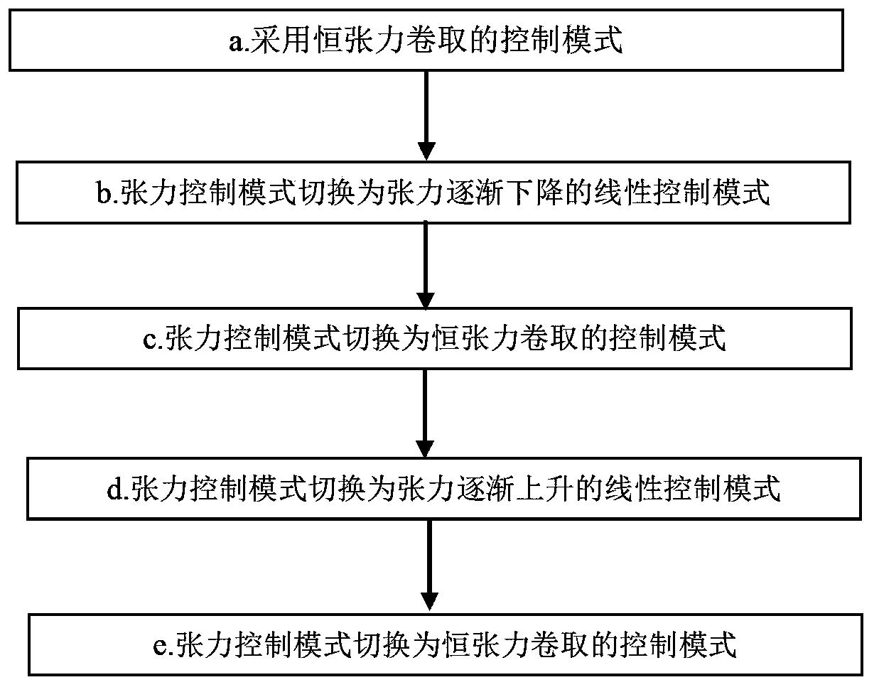
[0042] The present invention will be further described below in conjunction with the accompanying drawings and embodiments. as attached figure 2 Shown is the flow chart of the coiling method of the oriented silicon steel MgO coated steel coil of the present invention.

[0043] Set the second constant tension value Y2 of the steel coil as the main tension, the initial outer diameter X1 of the inner core of the steel coil, set the second outer diameter value X2, the third outer diameter value X3, the fourth outer diameter value X4 and the fifth The outer diameter value X5, and the outer diameter of the steel coil is monitored in real time, the ratio K1 of the first constant tension value Y1 of the inner layer of the steel coil to the second constant tension value Y2 and the ratio K1 of the outer layer of the steel coil are set. The ratio of the third constant tension value Y3 to the second constant tension value Y2 is the value of the tension taper coefficient K2. The setting...


PUM

PropertyMeasurementUnit
thicknessaaaaaaaaaa
thicknessaaaaaaaaaa
thicknessaaaaaaaaaa

Abstract

The invention relates to a coiling method of an oriented silicon steel MgO coated steel coil. The method comprises the following steps: 1, carrying out initial coiling on the steel coil on a coiler mandrel in a constant tension control coiling mode; 2, switching the tension control mode to a gradual decrease tension linear control mode; 3, switching the tension control mode to the constant tension control coiling mode; 4, switching the tension control mode to a gradual increase tension linear tension control mode; and 5, switching the tension control mode to the constant tension control coiling mode. The coiling method can effectively prevent the occurrence of coil collapse, inner and outer ring mandrel sideslip and other defects.

Description

technical field [0001] The invention relates to a coiling method for steel coils, in particular to a coiling method for oriented silicon steel MgO coated steel coils. Background technique [0002] The production process of oriented silicon steel in the silicon steel area is as follows: hot rolled coil → normalized pickling line (APL) → single stand cold rolling (RCM) → decarburization annealing line (DCL) → high temperature annealing line (BAF) → final coating annealing Unit (FCL)→finishing→packing and storage. Before the high-temperature annealing of the oriented silicon steel sheet, in order to prevent bonding and form the bottom layer of magnesium silicate, the upper and lower surfaces of the steel strip are coated with a layer of magnesium oxide coating with a certain degree of hydration at the exit of the decarburization annealing unit (DCL). , Although the coating is rolled into rolls after drying, there is still water in the coating. These waters will be released du...

Claims


Application Information

Patent Timeline
Patent Type & Authority Applications(China)
IPC IPC(8): C21D9/68C21D11/00
CPCC21D9/68C21D11/00C21D2251/02
Inventor 刘飞张荣康徐国忠谷维马光耀
Owner BAOSHAN IRON & STEEL CO LTD
Why Eureka
Try Eureka