Rotary-wheel-type small sewage treatment device

A sewage treatment device and runner-type technology, applied in the field of runner-type small sewage treatment devices, can solve the problems of long and heavy, laborious and time-consuming, trachea blockage, etc., and achieve the effect of less floor space and high treatment efficiency

Active Publication Date: 2015-02-18
ZHEJIANG CONSTR INVESTMENT ENVIRONMENTAL PROTECTION ENG CO LTD
View PDF5 Cites 2 Cited by
  • Summary
  • Abstract
  • Description
  • Claims
  • Application Information

AI Technical Summary

Problems solved by technology

[0003] 1. Oxygen in the air pressed into the sewage tank is not easy to dissolve in the sewage, so the aerobic bacteria on the pendant do not multiply quickly, and the sewage treatment efficiency is low
[0004] 2. The microorganisms attached to the biofilm of the pendant will multiply and absorb pollutants such as heavy metals and become longer and heavier. The activated sludge (membrane and bacterial corpse) will break and fall in pieces, causing the bottom trachea to be blocked
At this time, it is necessary to stop the operation to clean up the sludge, which is laborious and time-consuming
[0005] 3. After the air passes through the sewage, part of the oxygen dissolves into the sewage, and the remaining gas rushes out of the water surface, causing odor pollution to the surrounding environment
However, after the "artificial wetland" has been in operation for a period of time, each layer of filling will be blocked and cannot be used continuously.

Method used


Image

  • Rotary-wheel-type small sewage treatment device
  • Rotary-wheel-type small sewage treatment device
  • Rotary-wheel-type small sewage treatment device

Examples


Embodiment Construction

[0026] Further illustrate the present invention below in conjunction with accompanying drawing.

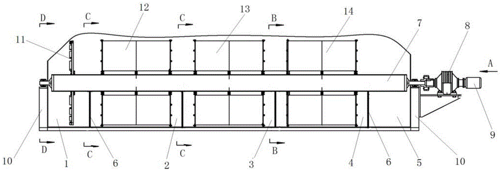
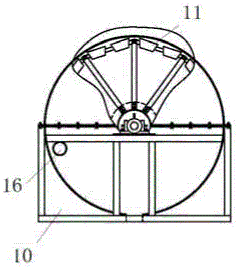
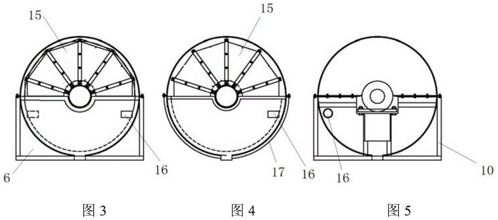
[0027] Referring to the accompanying drawings, the wheel-type small-scale sewage treatment device of the present invention comprises a horizontal cylindrical sewage bin, a main shaft 7, a motor 9, a reducer 8, and the lower semicircle of the cylindrical sewage bin is divided into five successively by a partition 6. Sub-bins 1-5 have water inlet and outlet 16 on the partition 6. The water outlet of the previous sub-bin is the water inlet of the next sub-bin. The water inlets and outlets of the five sub-bins have a drop in turn, so that sewage can flow in from the previous sub-bin. The next sub-position. The main shaft 7 is installed on the brackets 10 at both ends of the sewage tank through bearings, one end of the main shaft is fixed to the output shaft of the reducer 8, the input shaft of the reducer 8 is fixed to the rotating shaft of the motor 9, and the stirring wheel 11 is fi...


PUM


Abstract

The invention discloses a rotary-wheel-type small sewage treatment device which comprises a horizontal cylindrical sewage sump, a main shaft and a motor, wherein the lower semicircle of the sewage sump is divided into five branch sumps by partition boards, and water inlets/outlets on the five sump partition boards sequentially keep falls; a stirring wheel, a first rotary wheel, a second rotary wheel and a third rotary wheel are sequentially fixedly arranged on the main shaft, and are respectively arranged on the first, second, third and fourth branch sumps; the three rotary wheels are formed by splicing a plurality of wedged cages with trapezoidal cross sections, wherein the top surface of each wedged cage forming the first and the second rotary wheels is opened, the front and rear end faces of each wedged cage are provided with stainless steel plates respectively, and bottom surface and two side faces are provided with stainless steel screens; longitudinal and transverse corrugated plates which are distributed alternately fill up each wedged cage; the front and rear end faces of each wedged cage forming the third rotary wheel are provided with stainless steel screens respectively, and the top surface, the bottom surface and two side faces are provided with stainless steel plates; moreover, each wedged cage is filled with wood fragment packing; and an annular water fender is arranged on the front end face of each rotary wheel. The device disclosed by the invention is small in occupied space, high in sewage treatment efficiency and durable in operation.

Description

technical field [0001] The invention relates to a sewage treatment device, in particular to a small rotary wheel type sewage treatment device. Background technique [0002] At present, the structure of small-scale aerobic bacteria sewage treatment devices in my country is roughly as follows: a lot of well-shaped air pipes are arranged at the bottom of the horizontal cylindrical sewage tank, and many holes are drilled in the air pipes, and many pendants with aerobic bacteria attached to the top of the tank , Sewage slowly flows through the area densely covered with pendants, microorganisms will adsorb, oxidize, and macromolecular pollutants composed of nitrogen sources, carbon sources, phosphorus, etc. in the sewage, and decompose them into small molecules and absorb them as nutrients, thereby removing organic matter. During operation, the air compressor presses the air into the air pipe at the bottom of the sewage tank, and the holes on the air pipe allow the air to enter the...

Claims


Application Information

Patent Timeline
Patent Type & Authority Applications(China)
IPC IPC(8): C02F3/08C02F3/10
CPCY02W10/10
Inventor 王雍火梅真陈银康
Owner ZHEJIANG CONSTR INVESTMENT ENVIRONMENTAL PROTECTION ENG CO LTD
Why Eureka
Try Eureka