
Method for measuring inductance parameter of permanent magnet synchronous motor

A permanent magnet synchronous motor, inductance parameter technology, applied in the measurement device, measuring electrical variables, measuring resistance/reactance/impedance, etc. Measurement deviation accumulation and other problems, to achieve the effect of easy implementation, high measurement accuracy, and accurate inductance parameter measurement

Inactive Publication Date: 2015-02-18
CHANGCHUN INST OF TECH
View PDF7 Cites 24 Cited by
  • Summary
  • Abstract
  • Description
  • Claims
  • Application Information

AI Technical Summary

Problems solved by technology

[0005] The technical problem to be solved by the present invention is the inaccurate mechanical positioning of the d-axis of the motor during the measurement of the inductance parameters of the permanent magnet synchronous motor and the accumulation of measurement deviations caused by the integral algorithm; Problems such as inaccurate measurement of inductance parameters caused by current waveform distortion caused by dead zone and conduction voltage drop

Method used


Image

  • Method for measuring inductance parameter of permanent magnet synchronous motor
  • Method for measuring inductance parameter of permanent magnet synchronous motor
  • Method for measuring inductance parameter of permanent magnet synchronous motor

Examples


Embodiment 1

[0044] The purpose of the invention is to measure the inductance parameter of the permanent magnet synchronous motor through the three-phase short circuit of the motor.

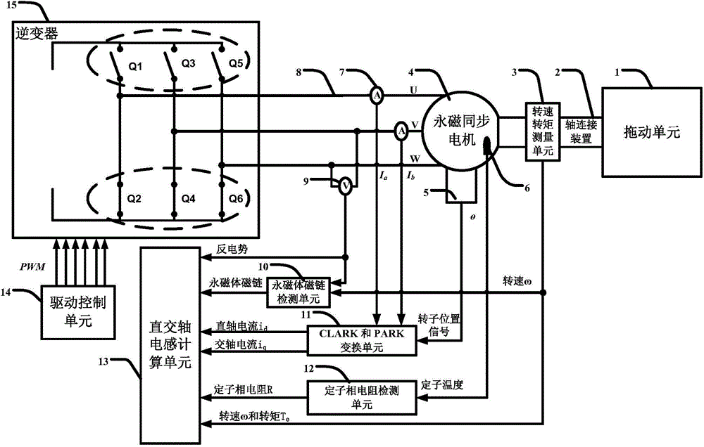
[0045] Such as figure 1 As shown, the drag unit 1 is used to drag the permanent magnet synchronous motor 4 to the set speed ω; the shaft connection device 2 is used to connect the mechanical interface between the drag unit 1 and the permanent magnet synchronous motor 4; the speed torque measurement unit 3 Used to measure the rotational speed ω and torque T of the mechanically connected shaft between the drag unit 1 and the permanent magnet synchronous motor 4 e The motor position sensor 5 is used to detect the absolute position of the motor rotor, which is an absolute position sensor, such as a resolver or an absolute position photoelectric encoder; the stator temperature sensor 6 is used to detect the motor stator temperature; the current sensor 7 is used to detect the phase current, It can be a non-contact...


PUM


Abstract

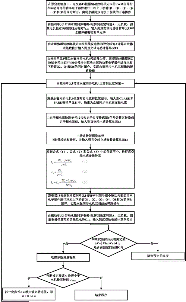
The invention relates to a method for measuring the inductance parameter of a permanent magnet synchronous motor, and belongs to the technical field of motor drive control. The problem of measured deviation accumulation caused by inaccurate mechanical locating of an axis d and an integral algorithm and inaccurate inductance parameter measurement caused by a dead zone and breakover drop voltages is solved. The method comprises the steps that at preset temperature, three-phase open circuit operation is carried out on the permanent magnet synchronous motor, the motor is driven to preset rotating speed through a dragging unit, counter electromotive force, permanent magnet flux linkage and stator resistance are measured, then three-phase short circuit operation is carried out, the physical characteristic that the rectangular axis voltage is zero is utilized, rectangular axis inductance is calculated through a rectangular axis voltage equation and a torque formula, the three-phase open circuit operation is carried out again, the counter electromotive force is measured, and whether rotor temperature is within an acceptable range or not is judged by measuring the changes of the front counter electromotive force and the rear counter electromotive force. According to the method, current waveform distortion caused by the dead zone of an inverter and the breakover drop voltages can be eliminated, d-axis mechanical locating is not needed, few mechanical devices are needed, and implementation is easy.

Description

technical field [0001] The invention belongs to the technical field of motor drive control and relates to a method for measuring inductance parameters of a permanent magnet synchronous motor. Background technique [0002] A typical motor drive control system consists of three parts: inverter, motor control and motor. The inverter is connected to the power battery or other types of power sources through fuses and relays, and converts direct current into alternating current through pulse width modulation technology (PWM) to drive loads. A current sensor is provided between the inverter device and the motor for detecting three-phase current. A sensor for detecting the position of the motor is installed on the motor. The motor control algorithm part can choose open-loop or closed-loop control according to the different requirements of the system. The closed-loop vector control based on field orientation has high precision, fast response and good robustness, so it has been wide...

Claims


Application Information

Patent Timeline
Patent Type & Authority Applications(China)
IPC IPC(8): G01R27/26
Inventor 曹艳玲曹萍刘国松
Owner CHANGCHUN INST OF TECH
Learn More