Permanent magnet speed controller with fixed magnetic gap

A technology of permanent magnet governor and fixed magnet, which is applied in the direction of controlling electromechanical brakes, electric brakes/clutches, electrical components, etc. It can solve the problems of high power consumption, poor torque transmission capacity, and waste of rare earth resources in magnetic circuit regulators. Achieve the effects of saving installation space, improving torque transmission capacity, and saving rare earth materials

Inactive Publication Date: 2015-02-18
刁俊起
View PDF5 Cites 1 Cited by
  • Summary
  • Abstract
  • Description
  • Claims
  • Application Information

AI Technical Summary

Problems solved by technology

At present, the commonly used permanent magnet governors realize the speed adjustment by adjusting the air gap. The power consumption of the magnetic circuit regulator is large, and there are disadvantages such as poor torque transmission capability, high assembly difficulty, and waste of a large amount of rare earth resources.

Method used


Image

  • Permanent magnet speed controller with fixed magnetic gap
  • Permanent magnet speed controller with fixed magnetic gap
  • Permanent magnet speed controller with fixed magnetic gap

Examples


Embodiment 1

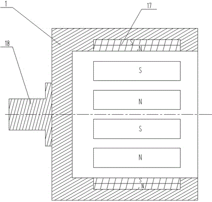
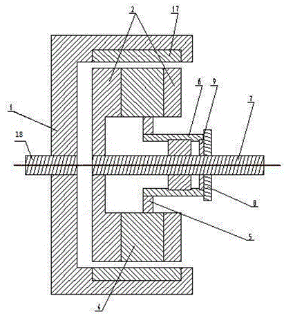
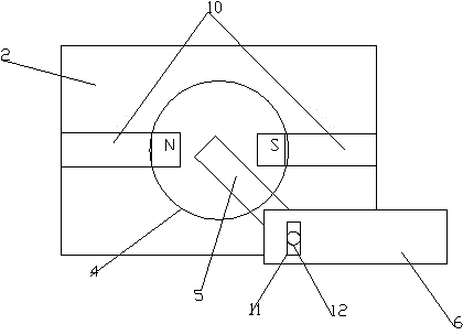
[0033] A permanent magnet governor with a fixed magnetic gap, such as figure 1 , 2As shown in . Magnets 17, the magnetic poles of the outer permanent magnets 17 are radially arranged, and the magnetic pole surfaces of the two adjacent outer permanent magnets 17 are different in magnetism; the inner magnetic rotor is distributed along its outer circumferential surface with at least one rotatable The permanent magnet 4, the rotatable permanent magnet 4 is perpendicular to the driven shaft 7. The rotatable permanent magnet 4 is cylindrical and has an N pole and an S pole along the diameter direction. The two sides of the rotatable permanent magnet 4 are wrapped with a magnetizer 2, and the two magnetizers 2 are separated by a non-magnetizer 10; In this embodiment, the number of magnets of the outer permanent magnet 17 is equal to the number of magnetic poles of the rotatable permanent magnet 4 . One end of the rotatable permanent magnet 4 is provided with a magnetic circuit re...

Embodiment 2

[0035] A permanent magnet governor with a fixed magnetic gap, such as figure 1 , 4 , 5, the rotatable permanent magnet 4 is parallel to the driven shaft 7, and other structures are the same as the first embodiment.

Embodiment 3

[0037] A permanent magnet governor with a fixed magnetic gap, such as figure 1 , 6 As shown in . Magnets 17, the magnetic poles of the outer permanent magnets 17 are radially arranged, and the magnetic pole surfaces of the two adjacent outer permanent magnets 17 are different in magnetism; the inner magnetic rotor is distributed along its outer circumferential surface with at least one rotatable The permanent magnet 4, the rotatable permanent magnet 4 is perpendicular to the driven shaft 7. The rotatable permanent magnet 4 is cylindrical and has an N pole and an S pole along the diameter direction. The two sides of the rotatable permanent magnet 4 are wrapped with a magnetizer 2, and the two magnetizers 2 are separated by a non-magnetizer 10; Two rotatable permanent magnets 4 are provided with a fixed permanent magnet 3 side by side along the axial direction of the driven shaft 7. The fixed permanent magnet 3 is cylindrical and has N poles and S poles along the diameter dire...


PUM


Abstract

The invention relates to a permanent magnet speed controller with a fixed magnetic gap. The permanent magnet speed controller comprises an outer magnet rotor and an inner magnet rotor, wherein at least two outer permanent magnets are uniformly distributed along the circumferential direction of the inner circumferential surface of the outer magnet rotor; the magnetic poles of the outer permanent magnets are arranged along the radial direction, and the magnetisms of exposed magnetic pole surfaces of every two adjacent outer permanent magnets are different; at least one rotatable permanent magnet is distributed along the circumferential direction of the outer circumferential surface of the inner magnet rotor; the rotatable permanent magnet is cylindrical, and the pole N and the pole S are arranged along the diameter direction; and one end of the rotatable permanent magnet is provided with a magnetic circuit regulator. Due to the adoption of the fixed magnetic gap, the meshing area of the speed controller is greatly increased, the assembling difficulty is lowered, the heat generation is reduced, the speed control range is widened, rare earth materials are saved, the torque transfer capacity is greatly improved, the function of controlling the speed at the input and output rotating speed of 0-N% is achieved, the material consumption is reduced, the mounting space is saved, and more importantly, the convenience is brought for field installation and construction.

Description

technical field [0001] The invention relates to a permanent magnet governor, in particular to a permanent magnet governor with a fixed magnetic gap. Background technique [0002] The permanent magnet speed governor uses the magnetic coupling speed of the permanent magnet to realize the soft (magnetic) connection between the motor and the load, without any harmonic generation affecting the power grid, and has high reliability. , Inflammable and explosive, voltage instability and lightning and other harsh environments, greatly reducing mechanical vibration, widely used in electric power, steel, metallurgy, petrochemical, papermaking, municipal, ships, irrigation and mining industries. At present, the commonly used permanent magnet governors realize the speed adjustment by adjusting the air gap. The magnetic circuit regulator consumes a lot of power, and has disadvantages such as poor torque transmission capability, high assembly difficulty, and waste of a large amount of rare ...

Claims


Application Information

Patent Timeline
Patent Type & Authority Applications(China)
IPC IPC(8): H02K51/00
CPCH02K49/106H02K2213/09H02K49/102H02P15/00H02P29/0027
Inventor 刁俊起
Owner 刁俊起
Why Eureka
Try Eureka