A vertical rotary gravity separation oil separation tank

A gravity separation and rotary technology, which is applied in the direction of liquid separation, separation method, grease/oily substance/floating matter removal device, etc., can solve the problem of reduced effective volume in the tank, long residence time, poor heat tracing and heat transfer effect To achieve the effect of avoiding complex flow field and "dead zone" of water flow, increasing gravity separation time and improving oil separation efficiency

Active Publication Date: 2015-12-30
JIANGSU AONISI ENVIRONMENTAL PROTECTION TECH +1
View PDF4 Cites 0 Cited by
  • Summary
  • Abstract
  • Description
  • Claims
  • Application Information

AI Technical Summary

Problems solved by technology

[0003] Grease trap and grease trap are two commonly used oil-water separation devices at present. The grease trap occupies a large area and has a small elevation, which is easily affected by the unevenness of water flow and the treatment effect is poor; Ratio, the elevation is significantly increased, the floor area is small, and the residence time is long. In addition to the effect of oil separation, it also has the effect of regulating homogeneity and buffering. Oil effect, but in the actual application process, there are still many disadvantages:
[0004] 1. The oil separation tank mainly uses the principle of gravitational degreasing due to the difference in density of oil and water. Single-stage oil separation is carried out in only the tank body, and the separation effect is not ideal;
[0005] 2. The structure of various pipelines in the tank is complex, resulting in extremely turbulent internal velocity field. There are many vortex flow, reverse mixed flow and flow "dead zone" in the tank, which leads to a decrease in the effective volume of the tank, affecting its own adjustment and oil-water separation effect ;
[0006] 3. The heating methods of the oil separation tank are mainly divided into direct heating and heat tracing. Direct heating is to pass steam into the dirty oil layer on the top. The heating speed is fast, but it is easy to cause oil splashing, the heat tracing and heat transfer effects are poor, and the energy consumption is relatively high. high

Method used


Image

  • A vertical rotary gravity separation oil separation tank
  • A vertical rotary gravity separation oil separation tank

Examples


Embodiment Construction

[0023] Below in conjunction with embodiment the present invention is described in further detail:

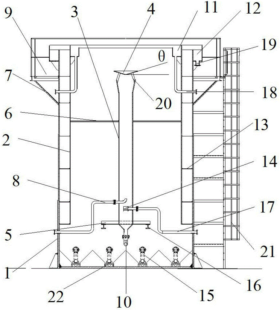
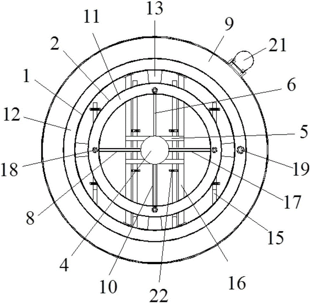
[0024] Such as figure 1 As shown, the vertical rotary gravity separation oil separation tank of the present invention includes an outer cylinder 1, an inner cylinder 2 is arranged inside the outer cylinder 1, and the tank wall of the outer cylinder 1 and the inner cylinder 2 is separated by 50 cm. Mounting and positioning plates 13 evenly distributed at 90° are arranged from bottom to top, and the bottom of the inner cylinder body 2 is 2.0m above the ground, and is fixedly supported by No. 2 H-shaped steel brackets 16 . The inner cavity of the inner cylinder body 2 is provided with a central water inlet tube 3, the inner diameter of which is 60cm, and is fixedly supported by the No. 1 H-shaped steel bracket 5, and the No. 1 H-shaped steel bracket spans and is fixed on the No. 2 H-shaped steel bracket 16 , there is a supporting angle iron 6 between the inner cylinder body 2 and ...


PUM

PropertyMeasurementUnit
diameteraaaaaaaaaa

Abstract

The invention discloses a vertical rotary type gravity-separation oil-separating tank which can be used for effectively improving oily water separating effects. The vertical rotary type gravity-separation oil-separating tank comprises an inner barrel body, an outer barrel body and a central water inlet barrel, wherein the inner barrel body is arranged inside the inner barrel body; the inner barrel body is communicated with the bottom of the outer barrel body; a height difference of 1.5-2.0m is formed between the bottom of the inner barrel and the ground; H-shaped steel is fixedly connected on the bottom of the inner barrel as support; a ring-shaped floating oil collecting slot which is equipped with an oil outlet tube is arranged on the top of the inner barrel; the oil outlet tube is uniformly distributed on the inner barrel wall at an angle of 90 degrees; an opening of the oil outlet tube penetrates through the inner and the outer barrel walls to the outside of the tank body; the central water inlet barrel is arranged in the cavity of the inner barrel body; a water inlet tube and a steam tube are connected at the lower end of the central water inlet barrel; an emptying tube is arranged on the bottom of the central water inlet barrel; three pipelines penetrate through the outer wall to the outside of the tank body through the bottom of the central water inlet barrel; the H-shaped steel is fixedly connected on the bottom of the central water inlet barrel as support; the H-shaped steel is spanned and fixed at the upper end of the support on the bottom of the inner barrel; a ring-shaped water outlet overflow slot and a passage are arranged on the top of the outer barrel; single water outlet tube is arranged on the bottom of the water outlet overflow slot; and a steel vertical ladder is arranged at one side of the barrel wall.

Description

technical field [0001] The invention relates to the technical field of an oily waste water oil separation device, in particular to a vertical rotary gravity separation oil separation tank. Background technique [0002] Production wastewater in petrochemical, manufacturing, food and textile industries has a large oil content and complex oil components. In addition to the oil quality of various reaction by-products, it also includes a large number of oil raw materials that enter the wastewater along with the production processes at all levels. Using appropriate technology to conduct preliminary oil separation treatment of wastewater and recycle the effective components in oil can reduce the production cost of the enterprise, indirectly improve the efficiency of the enterprise, and can also effectively avoid the reduction of biological activity caused by the oil film wrapping during the biological treatment of wastewater. Affect the final biological treatment effect. [0003] ...

Claims


Application Information

Patent Timeline
Patent Type & Authority Patents(China)
IPC IPC(8): C02F1/40
CPCC02F1/02C02F1/40
Inventor 梅凯肖雪峰陈烨王海涛程松董斌王政委王雄
Owner JIANGSU AONISI ENVIRONMENTAL PROTECTION TECH
Why Eureka
Try Eureka