Cup grinding wheel variable-positioning-base-circle convex surface workpiece grinding method

A cup-shaped grinding wheel and curved workpiece technology, which is applied in the field of convex curved workpiece grinding, can solve the problems of inability to guarantee the machining accuracy, the influence of machining accuracy, and the wear of the grinding wheel, so as to increase the surface utilization rate, improve the processing efficiency, and avoid the grinding wheel. trimming effect

Active Publication Date: 2015-03-04
TIANJIN UNIV
View PDF6 Cites 8 Cited by
  • Summary
  • Abstract
  • Description
  • Claims
  • Application Information

AI Technical Summary

Problems solved by technology

Moreover, the second forming method solves the low efficiency problem of the first method, but due to the serious wear of the grinding wheel during the processing, the machining accuracy cannot be guaranteed after the positioning points on the end surface of the grinding wheel are worn, which affects the overall machining accuracy
[0003] The application publication number is 102528663A "The processing method of the convex function rotary part with the straight line envelope of the variable forming point", which provides a variable variable shape for solving the technical problems in the processing of the convex function rotary part. The processing method of the molding point, which uses the outer circular surface of the flat grinding wheel for grinding, and compensates the error caused by the wear of the molding point by continuously changing the molding point on the grinding wheel, so as to ensure the grinding efficiency and improve the grinding accuracy , but this method is only applicable to the machining of rotary workpieces whose generatrices are convex function curves, and cannot process non-rotary convex surface workpieces, and the above method is only suitable for three-axis CNC lathe processing

Method used


Image

  • Cup grinding wheel variable-positioning-base-circle convex surface workpiece grinding method
  • Cup grinding wheel variable-positioning-base-circle convex surface workpiece grinding method
  • Cup grinding wheel variable-positioning-base-circle convex surface workpiece grinding method

Examples


Embodiment 1

[0049] To process k9 glass workpiece, use resin bonded corundum cup-shaped grinding wheel, the diameter of the end face of the grinding wheel is 5cm, and the particle size of the grinding wheel is 120#, and it is processed on a five-axis machining center. The specific processing steps are as follows:

[0050] To process the quadratic surface of the glass workpiece, set its expression as (under the workpiece coordinate system):

[0051]

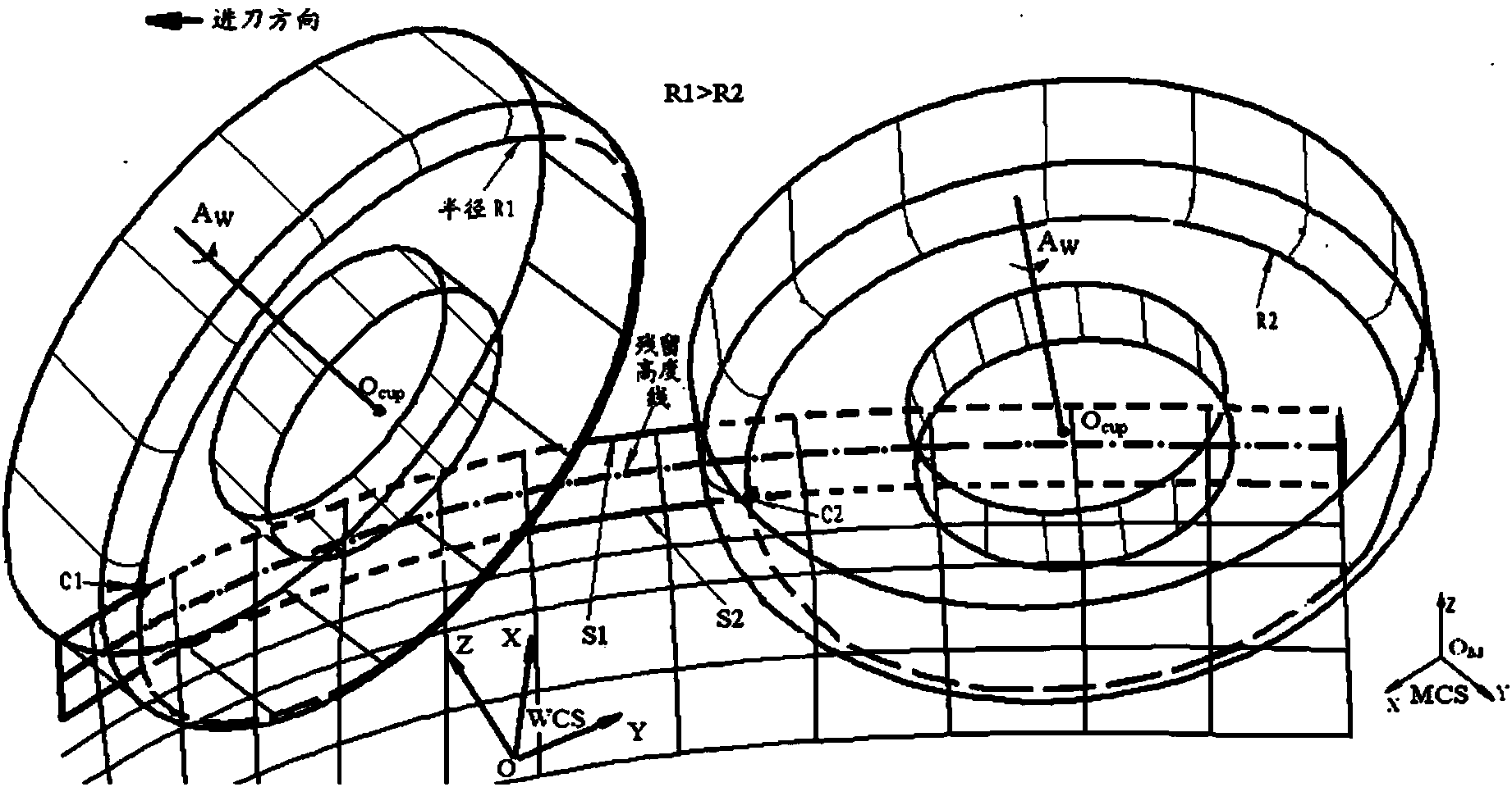
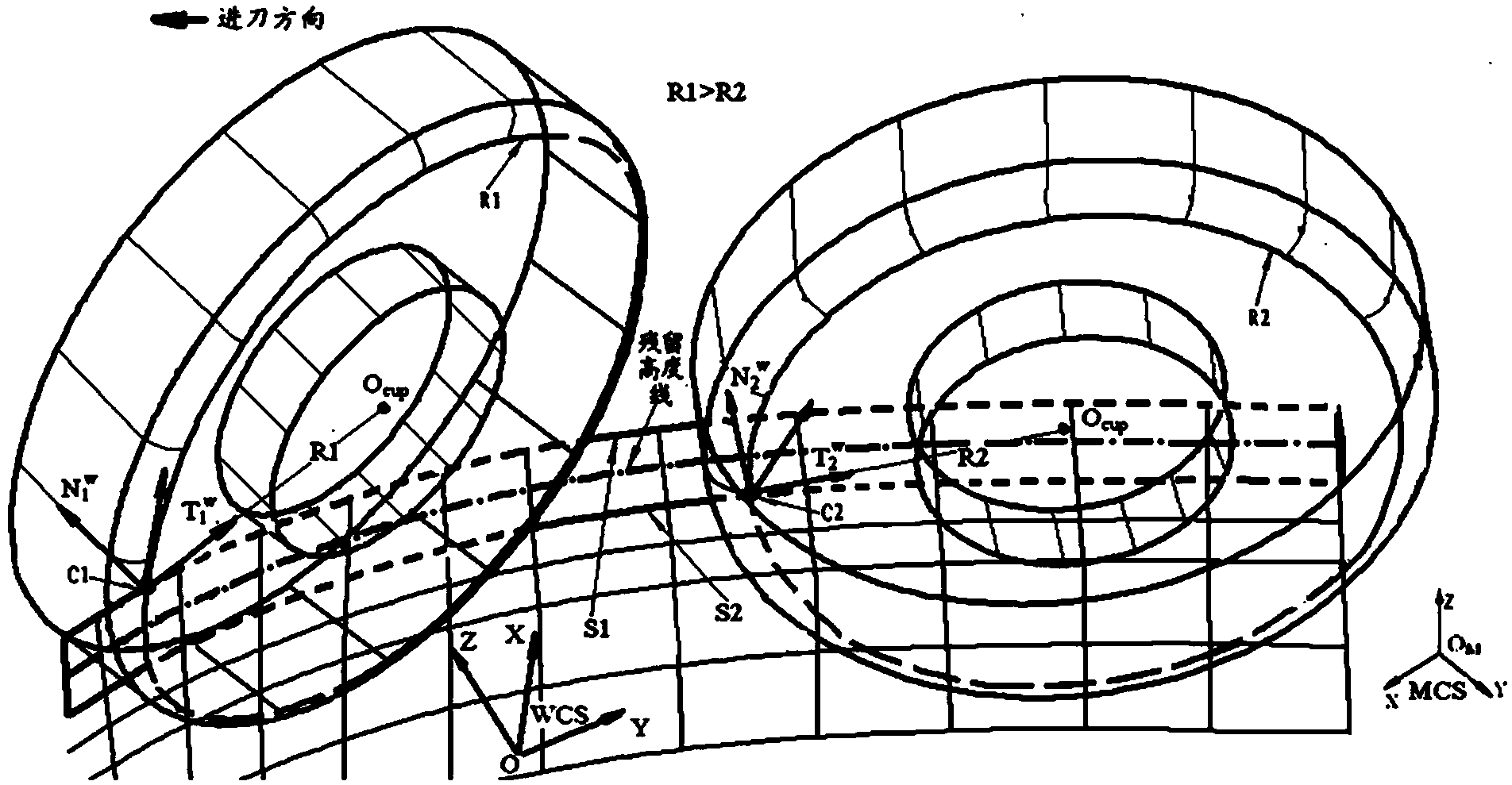
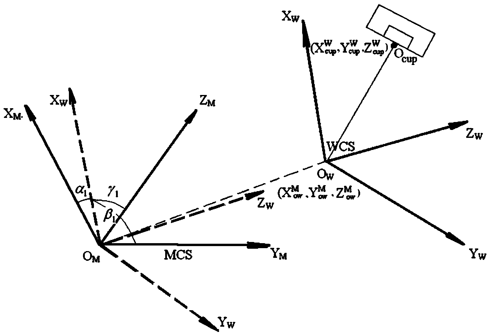
[0052] A cup-shaped grinding wheel installed on a five-axis linkage CNC machine tool is used to process the above-mentioned convex surface workpiece. During the processing, the control system of the CNC machine tool outputs a control signal to the cup-shaped grinding wheel to make the cup-shaped grinding wheel process along the grinding track, and control The system outputs the central point running trajectory control signal to control the movement trajectory of the center point of the end face of the cup-shaped grinding wheel, so that the ...


PUM


Abstract

The invention discloses a method for machining a convex surface workpiece by using a cup grinding wheel installed on a five-axis linkage numerical control machine, a control system of the numerical control machine outputs a control signal during machining to control the cup grinding wheel to machine along a grinding trajectory, and the control system further outputs a center point running trajectory control signal to control the moving trajectory of the center point of the end surface of the cup grinding wheel such that the radius of a positioning base circle using the center point of the end surface of the cup grinding wheel as a circle center and a connecting line with a contact point as a radius is gradually reduced with change of machining time and cutting amount and the contact point is always guaranteed to be an unworn point on the end surface of the grinding wheel; the control system simultaneously outputs an angle control signal such that the end surface of the grinding wheel is always in tangent contact with the machined convex surface by adjusting the angle of the axis of revolution of the grinding wheel, the contact point is located on the grinding trajectory and the angle of the axis of revolution of the grinding wheel is consistent with the normal vector of the machined convex surface at the tangent contact point. By adopting the method, not only can the machining efficiency be improved, but also the machining accuracy is improved.

Description

technical field [0001] The invention relates to a workpiece grinding method, in particular to a convex curved surface workpiece grinding method. Background technique [0002] With the advancement of science and technology, hard and brittle materials such as engineering ceramics and optical glass have been widely used in aerospace, biotechnology, optical engineering and other fields. Due to their high hardness and high precision requirements, their processing is very difficult. The main processing method used now is to use the tool nose trajectory of the grinding wheel to grind the shape and the end face of the cup-shaped grinding wheel to grind the free convex surface workpiece. Both methods can control the machining accuracy and surface quality by controlling the distance between two tool paths. Moreover, the second forming method solves the low efficiency problem of the first method, but due to the serious wear of the grinding wheel during the processing, the machining a...

Claims


Application Information

Patent Timeline
Patent Type & Authority Applications(China)
IPC IPC(8): B24B19/00B24B51/00
CPCB24B19/009B24B49/165
Inventor 林彬王少雷
Owner TIANJIN UNIV
Why Eureka
Try Eureka