Circuit and method for synchronous rectification of Jensen circuit

A technology of synchronous rectification and full-wave rectification circuit, which is applied in the direction of high-efficiency power electronic conversion, electrical components, and adjustment of electrical variables, and can solve the problems of inability to realize soft switching technology, complex circuits, and low efficiency

Active Publication Date: 2015-03-04
MORNSUN GUANGZHOU SCI & TECH
View PDF10 Cites 4 Cited by
  • Summary
  • Abstract
  • Description
  • Claims
  • Application Information

AI Technical Summary

Problems solved by technology

[0028] 1. The efficiency is low, because: the soft switching technology cannot be realized, and the self-driven synchronous rectification cannot be realized with a simple circuit;
[0029] 2. After the working frequency increases, the efficiency decreases
However, it loses the simple characteristics of Jingsen circuit, and the reliability is greatly reduced due to the complexity of the circuit.

Method used


Image

  • Circuit and method for synchronous rectification of Jensen circuit
  • Circuit and method for synchronous rectification of Jensen circuit
  • Circuit and method for synchronous rectification of Jensen circuit

Examples


no. 1 example

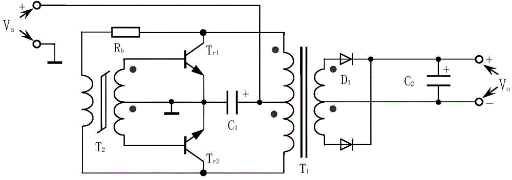
[0098] see Figure 5 . First show the circuit parameters and measured performance of the existing technology, Figure 5 The Jingsen circuit is designed as a converter with an input of 48V and an output of 12V / 1A: the resistor R1 is 33K, the resistor Rb is 16K, the capacitor C1 is 0.047uF / 16V, the parameters of the switch tube: both the triode TR1 and TR2 are FZT853, the withstand voltage Only 100V, the measured value is more than 130V, used in the circuit, the test is not a big problem. Capacitor C is a 10uF / 63V electrolytic capacitor, the output uses Figure 6 The full-wave rectification circuit, the diodes D1 and D2 both use 2A / 40V Schottky diodes, and the output filter capacitor C2 uses 10uF / 25V tantalum capacitors; among them, the magnetic saturation transformer B1 uses Tiantong’s TS7 ring core , the initial magnetic permeability is 7500, the outer diameter is 5.05mm, the inner diameter is 2.3mm, the thickness is 1.6mm, the primary side winding is 49 turns, the secondar...

no. 2 example

[0137] see Figure 14 ,and Figure 8 The difference is that the capacitors C1 and R1 are connected in parallel. Paragraphs 0029 to 0035 of the Chinese patent 201210174076.7 discuss that this method only affects the startup and does not affect the normal operation. Figure 14 The Jingsen circuit is designed as a converter that inputs 24V and outputs 5V / 0.2A:

[0138] The resistor R1 is 27K, the resistor Rb is 18K, the capacitor C1 is 0.1uF / 10V, the parameters of the switch tube: the triode TR1 and TR2 are both FMMT493, the withstand voltage is only 150V, and the current is 1A. The output filter capacitor C2 adopts a 2.2uF / 10V chip capacitor; the output adopts a synchronous rectification full-wave rectification circuit, and the full-wave rectification circuit includes the first N-type field effect transistor Q1 and the second N-type field effect transistor Q2; Q1 and Q2 All are XP151A13AOMR N-type FETs with a withstand voltage of 20V and a current of 1A, that is, N-channel FET...

no. 3 example

[0150] see Figure 15 ,and Figure 8 The difference is that a resonant capacitor Cd is connected in parallel with both ends of the primary winding of the drive transformer B1, Figure 15 The Jingsen circuit is designed as a converter with an input of 48V and an output of 12V / 1A. The capacitor Cd is an NPO capacitor of 270pF, and the withstand voltage is 1000V; other parameters are the same as those of the first embodiment of the present invention. After the circuit is welded, its performance is energized and tested:

[0151] The peak-peak value of the AC working voltage at both ends of the primary winding of the saturated transformer is: 272.1V;

[0152] Output no-load static power consumption: 0.24W;

[0153] Full load conversion efficiency: 95.1%;

[0154] Working frequency: 274.9KHz.

[0155] After a resonant capacitor Cd is connected in parallel to both ends of the primary winding of the drive transformer B1, in the solution shown in the third embodiment, its operating...


PUM


Abstract

The invention provides a circuit and a method for synchronous rectification of a Jensen circuit. A secondary winding with a central tab is added to a driver transformer B1 to drive synchronous rectification MOS tubes Q1 and Q2 arranged in a secondary rectifier circuit; the magnet and the number of primary turns of the driver transformer B1 are optimized, the impedance of a feedback resistor is optimized, and the working voltage at the two ends of the primary side of the driver transformer B1 is changed into sine wave or approximate sine wave from the existing square wave; the turn ratio of the first and second secondary windings of the driver transformer B1 is adjusted according to the on voltages of the synchronous rectification MOS tubes so that the on time of the MOS tubes Q1 and Q2 is always smaller than the saturated on time of main power switch tubes TR1 and TR2, and therefore, the reverse current is eliminated; meanwhile, a main transformer B2 is excited during the period of both main power switch tubes TR1 and TR2 off by use of the sine wave in the driver transformer B1, and therefore, the main power switch tubes TR1 and TR2 are switched on under zero voltage and soft switching working is realized; as the synchronous MOS tubes are switched off firstly, the main power switch tubes are also switched off under zero current; the conversion efficiency is improved and the high reliability of the simple Jensen circuit is also maintained.

Description

technical field [0001] The invention relates to a self-excited push-pull converter, in particular to a wellmori circuit and method for realizing synchronous rectification. Background technique [0002] The existing self-excited push-pull converters are generally divided into two categories: Royer circuit and Weller circuit. [0003] The Royer circuit comes from the self-excited oscillating push-pull transistor single-transformer DC converter invented by G.H.Royer in 1955, usually referred to as the Royer circuit, which is also the beginning of the realization of high-frequency conversion control circuits; Jen Sen, most of the literature is translated as "Jingsen") invented the self-excited push-pull double transformer circuit, which was later called the self-oscillating Jensen circuit, the self-excited push-pull Jensen circuit, and most of the literature is called the Jingsen circuit; Both circuits are called self-excited push-pull converters. [0004] The self-excited pus...

Claims


Application Information

Patent Timeline
Patent Type & Authority Applications(China)
IPC IPC(8): H02M3/337
CPCH02M3/3382H02M3/3387Y02B70/10
Inventor 王保均
Owner MORNSUN GUANGZHOU SCI & TECH
Why Eureka
Try Eureka