Control method achieving tension feedback and joint position feedback and used for flexibility driving unit for robot joint

A technology of robot joints and drive units, which is applied to the control of flexible drive units for robot joints and the field of control of flexible drive units for robot joints. It can solve the problems of large control errors, inability to realize tension feedback and full closed-loop control of joints, etc.

Active Publication Date: 2015-03-11
HARBIN INST OF TECH
View PDF5 Cites 19 Cited by
  • Summary
  • Abstract
  • Description
  • Claims
  • Application Information

AI Technical Summary

Problems solved by technology

The application number is 201410257786.5, a flexible drive unit for robot joints driven by ropes, powered by moving pulleys, equipped with tension sensors and joint encoders, does not provide an effective control method, and cannot realize tension feedback and Fully closed-loop control of the joints, there is a problem of large control errors

Method used


Image

  • Control method achieving tension feedback and joint position feedback and used for flexibility driving unit for robot joint
  • Control method achieving tension feedback and joint position feedback and used for flexibility driving unit for robot joint
  • Control method achieving tension feedback and joint position feedback and used for flexibility driving unit for robot joint

Examples


specific Embodiment approach 1

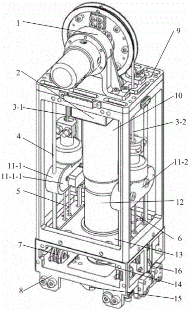
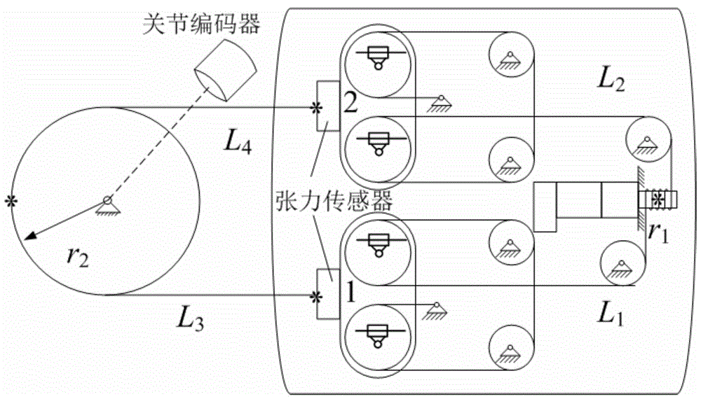
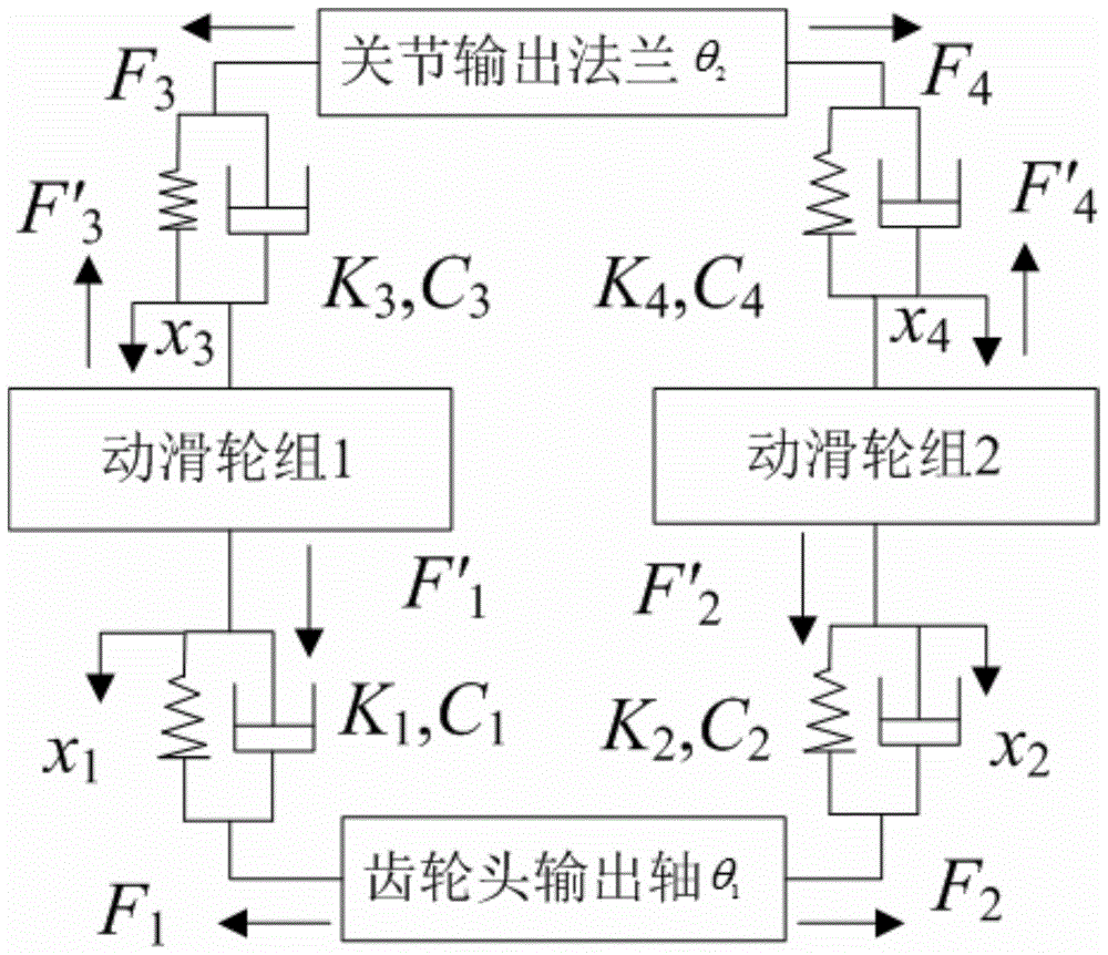
[0069] Specific implementation mode one: as Figure 1-11 As shown, the flexible drive unit control method for robot joints described in this embodiment that can realize tension feedback and joint position feedback uses the viscoelastic dynamics model of the flexible drive unit to perform joint position and joint speed feedback, and performs the feedback according to the elastic deformation of the steel wire rope. Feedforward for joint velocity and joint acceleration. Joint position and speed feedback, that is, the position loop and speed loop of the joint are introduced on the basis of the internal position loop and speed loop of the motor to realize the full closed-loop control of the joint of the flexible drive unit. For the speed and acceleration feedforward of elastic deformation, the basic idea is that the elongation of the steel wire rope can be obtained through the elastic deformation formula, and the speed and acceleration that need to be fed forward can be obtained fr...

specific Embodiment approach 2

[0109] Specific implementation mode two: the block diagram of the controller designed according to the control method and its principle diagram are as follows Figure 4 shown. The solid line part is the classic PID servo control link, and the dotted line part is the supplementary control link according to the control method. The controller generates the joint angle and angular velocity sequence through the trajectory generator of the host computer, and sends it to the motion control card for servo interpolation calculation. Before the servo interpolation calculation, the joint angle and angular velocity are fed back first. Carry out four arithmetic operations and differentiation on the joint angle formula derived from science, and the obtained joint angle and angular velocity estimates are used to feed back the joint reference angle and angular velocity; after the servo interpolation calculation, the velocity and acceleration are fed forward. The deformation of the steel wire ...

specific Embodiment approach 3

[0110] Specific implementation mode three: Application example 1 of this patent, that is, the hardware photo of the flexible drive unit control system built according to the control method is as follows Figure 5 As shown in a), the schematic diagram is as follows Image 6 shown. The upper computer performs trajectory planning and sends the planned instructions to the PMAC motion control card. The PMAC motion control card communicates with the upper computer through Ethernet and sends the motion program to the PMAC. The PMAC can upload the program or system status to the upper computer; The driver is controlled by PFM mode, the driver amplifies the signal and sends it to the motor; the motor encoder A phase, B phase, I (index) signal is fed back to the driver and PMAC motion control card at the same time; the joint encoder feeds back the A, B, I signal to The PMAC card constitutes a fully closed-loop control; the enable control of the motor driver is performed according to th...


PUM


Abstract

The invention discloses a control method achieving tension feedback and joint position feedback and used for a flexibility driving unit for a robot joint and belongs to the field of robot application and control. The invention aims to realize the tension feedback and the joint full-closed loop control of the flexibility driving unit for the robot joint so as to reduce flexibility driving joint control errors and improve system frequency response. The method discloses a control strategy based on viscoelasticity kinetic model compensation and gives the design of the flexibility driving unit controller. A front feed controller is designed according to a steel wire elastic deformation formula and a feedback controller is designed according to a motor angle estimate value formula. The design method is suitable for the design of a controller of the flexibility driving unit for the robot joint. Hardware of a flexibility driving unit control system is constructed, joint position feedback is performed through a joint encoder and motor position feedback is performed by utilizing motor position estimated values, so that full closed-loop position control of the control system of the driving unit is realized. Compared with a classic PID(Proportion Integration Differentiation) control method, servo control precision can be improved distinctively, tracking errors can be reduced and system frequency response can be improved.

Description

technical field [0001] The invention relates to a control method of a flexible drive unit for a robot joint, in particular to a control method for a flexible drive unit for a robot joint that is suitable for rope drive, dynamic pulley force augmentation, tension and joint position feedback, and belongs to robot application control field. Background technique [0002] Compared with the rigid drive, the wire rope flexible drive can absorb vibration and reduce the impact. However, due to the large joint hysteresis and obvious hysteresis, the classic PID control method is not effective. After literature search, it is found that the Chinese patent announcement number is CN101863034B, the patent number is 201010210888.3, ​​and the name is a flexible drive unit for a robot joint driven by a pulley block and a wire rope traction. It is a rope-driven joint flexible drive unit, but no control method is given. The application number is 201410257786.5, a flexible drive unit for robot j...

Claims


Application Information

Patent Timeline
Patent Type & Authority Applications(China)
IPC IPC(8): B25J9/16
CPCB25J9/16
Inventor 吴伟国侯月阳
Owner HARBIN INST OF TECH
Why Eureka
Try Eureka