Method for increasing separation efficiency of oil field associated gas and recovering carbon dioxide

A technology for oilfield associated gas and carbon dioxide, applied in the chemical industry, can solve the problem of low recovery efficiency of oilfield associated gas, achieve the effects of continuous and stable separation process, reduce processing load and improve light hydrocarbon recovery rate

Active Publication Date: 2015-03-11
DALIAN UNIV OF TECH
View PDF4 Cites 16 Cited by
  • Summary
  • Abstract
  • Description
  • Claims
  • Application Information

AI Technical Summary

Problems solved by technology

[0005] In order to solve the problem of low recovery efficiency of oilfield associated gas using gas injection technology, the present invention provides a method for improving the separation efficiency of oilfield associated gas and recovering carbon dioxide. The method is characterized in that the tail gas (non-condensable gas) produced by compression condensa...

Method used


Image

  • Method for increasing separation efficiency of oil field associated gas and recovering carbon dioxide

Examples


Embodiment 1

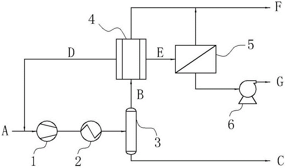
[0022] Please combine the attached figure 1 , In this embodiment, the membrane materials of the double-membrane separator 4 are respectively PEI and PDMS. The pressure of oilfield associated gas A is 150kPa. After being pressurized by compressor 1 to 1500kPa and cooled to -30°C by condenser 2, the gas-liquid phase is separated by liquid separation tank 3 to obtain light hydrocarbons B and non-condensable gas C. The non-condensable gas C enters the double-membrane separator 4 after pretreatment to obtain hydrocarbon-rich gas D, carbon-rich gas E and natural gas F. The hydrocarbon-rich gas D has a pressure of 150kPa and is sent back to the compression condensation system 1 to increase the yield of light hydrocarbons; the carbon-rich gas E has a pressure of 150kPa and enters the single-membrane separator 5 . The single-membrane separator 5 further purifies the enriched carbon dioxide, and the retentate gas is combined with natural gas F. The inlet gas pressure of the vacuum pum...

Embodiment 2

[0026] Please combine the attached figure 1 , operating process and operating conditions are the same as in Example 1. In this embodiment, PI and PTMS are used as the membrane materials of the double-membrane separator 4 respectively. In this embodiment, the recovery rate of light hydrocarbons is 60%, the production of oil displacement gas is 1379kg / h, and the purity of carbon dioxide reaches 99%.

[0027] Table 2 embodiment 2 material balance

[0028]

Embodiment 3

[0030] Please combine the attached figure 1 , the operating process is the same as in Example 1; the outlet pressure of the compressor is raised to 2000kPa, and other operating conditions are the same as in Example 1. In this embodiment, the membrane materials of the double-membrane separator 4 are respectively PEI and PDMS. In this embodiment, the recovery rate of light hydrocarbons is 69%, the production of oil displacement gas is 1392kg / h, and the purity of carbon dioxide reaches 99%.

[0031] Table 3 embodiment 3 material balance

[0032]


PUM


Abstract

The invention relates to a method for increasing separation efficiency of oil field associated gas and recovering carbon dioxide, which belongs to the technical field of chemical industry. A double-membrane separator is used for increasing the processing efficiency of oil and gas field associated gas, and the invention provides a high efficiency oil-removal agent for displacing oil of the oil field. The double-membrane separator is used for respectively purifying light dydrocarbon and carbon dioxide in non-condensable gas, and three effects that light hydrocarbon recovery efficiency can be increased, apparatus operation load due to carbon dioxide is reduced and natural gas decarburization is reduced can be realized in same apparatus, a carbon dioxide separating membrane is used for purifying carbon dioxide and can be used for displacing oil injection. The method can effectively reduce the influence of carbon dioxide on a associated gas recovery device, apparatus operation cost is reduced, light hydrocarbon yield can reach more than 30%, concentration of natural gas carbon dioxide is reduced to less than 2%. The natural gas loss late is less than 0.5%, the apparatus is simple and compact, and is suitable for on-line production, and the economic benefit is high.

Description

technical field [0001] The invention belongs to the technical field of chemical industry, and relates to a device and method for improving the separation efficiency of oilfield associated gas and recovering carbon dioxide, and in particular to a comprehensive process for recovering light hydrocarbons from oilfield associated gas and decarbonizing natural gas. Background technique [0002] Oilfield associated gas is natural gas extracted together with oil and gas. With the increasing depletion of oil resources, the recovery and utilization of high-value light hydrocarbon components has become an important means to increase oilfield output value. The most commonly used separation method for light hydrocarbon components of oilfield associated gas is compression condensation technology, which increases the dew point of associated gas through pressurization, and lowers the temperature to achieve gas-liquid separation, thereby efficiently recovering light hydrocarbon components. U...

Claims


Application Information

Patent Timeline
IPC IPC(8): C10L3/10C10G5/06B01D53/22B01D53/00C01B31/20C01B32/50
CPCY02C20/40Y02P20/151
Inventor 贺高红陈博阮雪华肖武
Owner DALIAN UNIV OF TECH
Why Eureka
Try Eureka